


Chapter 1: Product Description December 20, 2004
1-4 LTPH-UM-1261-01
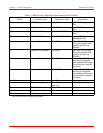
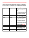
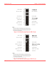
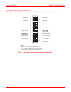
Table 1-1. HMS-318 List 3 Shelf Rear-Panel Connections (LPS-300C)
Connector/Terminal
Block Connector Type Connectory Label Description
J24 BNC-T (Female) 10 BASE-2 10BASE-2 Management
Port
J25 RJ-45 10 BASE-T 10BASE-T Management
Port
J26 RS-232 DB-25 (Female) OS RS232 DTE PORT RS-232/X.25 Management
Port
J27 RS-232 DB-25 (Female) AUX RS232 DTE PORT Auxiliary RS-232
Management Port
P1 Amphenol 50-pin (Male) CO PAIR 1 DS1/xDSL B IN Tip and
Ring (non-powered xDSL
signal to and from the
DSLAM)
P2 Amphenol 50-pin (Male) CO PAIR 2 DS1/xDSL A IN Tip and
Ring (non-powered xDSL
signal to and from the
DSLAM)
P3 Amphenol 50-pin (Male) SPAN PAIR 1 HDSL/xDSL A OUT Tip
and Ring (bi-directional
span powered xDSL signal
to and from the Customer
Premises)
P4 Amphenol 50-pin (Male) SPAN PAIR 2 HDSL/xDSL B OUT Tip
and Ring (bi-directional
span powered xDSL signal
to and from the Customer
Premises)
J1 - J22 20-pin wire-wrap J1 - J22 HLU connectors
J1 - J22 20-pin wire-wrap J1 - J22 (odd-numbered
slots only)
LPS-300C connectors
J23 DIN 96-pin (Female) J23
HMU connector
a
a.Not used in LPS-300C Power Module configuration.
TB1 5-position terminal block TB1 Input Power connector
TB2 26-pin wire-wrap field Alarms Alarm connector