


Chapter 2: Installation December 20, 2004
2-8 LTPH-UM-1261-01
DSX and HDSL Connector Procedure
SPAN POWERED XDSL CONNECTIONS
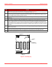
Perform the following procedure to connect the Span Powered xDSL interface cables to connectors P1, P2, P3 and
P4 (see Figure 1-2 on page 1-3 for connector location and “Connecting Span Powered xDSL Circuits to the HMS-
318 List 3 Shelf” on page 1-10 for connector descriptions).
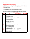
Span Powered xDSL Connector Procedure
Step Action
1 Complete one of the following steps to make the DSX-1 and HDSLx connections to the shelf using one of
the following methods: Plug the DSX-1 interface cables into P1 and P2 and the HDSLx interface cables
into P3 and P4. Wire-wrap the DSX-1 and HDSLx inputs to the appropriate individual card slots. Pin
assignments are listed in Appendix A: “Signal and Pin Assignments” on page A-1.
2 Continue to “Bonding (Safety) Ground, Power and Frame Ground, Alarm, and Optional Fan Inputs” on
page 2-9.
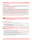
DANGER
Before making any Span Powered xDSL connections to the HMS-318 List 3 shelf, ensure that the
Main CO power breaker is off. Otherwise, severe injury to the installer or damage to the unit may
result.
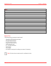
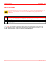
Step Action
1 Complete one of the following steps to make the Span Powered xDSL connections to the shelf using one
of the following methods:
• Plug the Span Powered xDSL interface cables into P1, P2, P3 and P4.
• Wire-wrap the Span Powered xDSL inputs to the appropriate individual card slots. Pin assignments
are listed in Appendix A: “Signal and Pin Assignments” on page A-1.
2 Continue to “Bonding (Safety) Ground, Power and Frame Ground, Alarm, and Optional Fan Inputs” on
page 2-9.
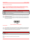
Note: See Figure 1-2 on page 1-3 for the location of the HDSLx Span connectors. HDSLx Span
pin assignments are listed in Appendix A: “Signal and Pin Assignments” on page A-1. Standard
PIC cable color codes are listed in Appendix B: “Standard PIC Color Code” on page B-1.
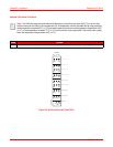
Note: See Figure 1-2 on page 1-3 for the location of the HDSL Span connectors. HDSL Span
pin assignments are listed in Appendix A: “Signal and Pin Assignments” on page A-1.
Standard PIC cable color codes are listed in Appendix B: “Standard PIC Color Code” on
page B-1.