


December 20, 2004 Chapter 2: Installation
LTPH-UM-1261-01 2-13
INSTALLING THE HMU-319 WITH HLU-319, H2TU-C-319, H4TU-C-319
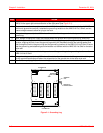
Install the line units (HLUs) into slots 1 through 22 and the HMU-319 management unit into slot 23 of the HMS-318
List 3 shelf (see “HMS-318 List 3 Shelf - Front View” on page 1-2 for slot location).
Install HMU and HLU Procedure
INSTALLING LPS-300C POWER MODULE
Install the LoopStar (LPS-300C) Power Modules into slots 1 through 22 [odd numbered slots (1, 3, 5, 7, ... 21) ] of
the HMS-318 List 3 shelf (see Figure 1-2 on page 1-3 for slot location, “Connecting Span Powered xDSL Circuits to
the HMS-318 List 3 Shelf” on page 1-10 for Span Powered xDSL Circuit connection, and Appendix A: “Signal and
Pin Assignments” on page A-1 for pin assignments).
ATTENTION
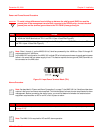
Use anti-static wrist-straps connected to the ESD Jack (located on the right adapter bracket, see
Figure 1 on page 3) when inserting a circuit card. Avoid touching components on the circuit card.
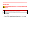
Step Action
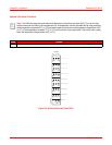
1 Hold the HLU and HMU vertically with the front of the circuit card toward you. Align the top and bottom
edges of the HLU and HMU with the HMS-318 List 3 shelf slot guides.
2 Slide the HLU and HMU into their respective slots.
3 Press the HLU and HMU firmly into the connector until it is seated into the edge-connector on the shelf
backplane.
Note: The HLU and HMU will power up with various status LEDs and displays indicating power up status
(refer to the HLU-319, H2TU-C-319, or H4TU-C-319 Technical Practice and HMU-319L7V32 and L9V32
User Manual, catalog number LTPH-UM-1142 in the “Related Publications” on page ix for the proper
power-up descriptions).
For visual and audible alarm contact operation, install an HMU-319. Refer to HMU-319 L7AV32 and L9V32
User Manual (LTPH-UM-1142).