


Chapter 2: Installation December 20, 2004
2-4 LTPH-UM-1261-01
SAFETY GUIDELINES
The safety guidelines (see Chapter 1: “Safety Guidelines” on page 1-iv) are provided to help ensure your safety and
to protect your equipment. The list on page iv may not identify all potentially hazardous situations in your working
environment, so be alert and exercise good judgment at all times.
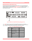
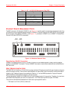
MOUNTING THE HMS-318 LIST 3 SHELF
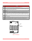
Each HMS-318 List 3 shelf has a hardware kit. The rack adapter brackets are attached to the HMS-318 List 3 shelf
at the factory. They are supplied with the shelf to allow mounting on 19-inch (48.3-cm) telco-style EIA or WECO
equipment racks. Select the appropriate position for the brackets (2 or 5 inches) and mount the shelf to the bracket
as described in the Chapter 2: “Adapter Bracket Mounting Procedure (19-inch Telco-style Equipment Rack)” on
page 2-5 and the Chapter 2: “Adapter Bracket Mounting Procedure (23-inch Telco-style Equipment Rack)” on
page 2-5. When installed in an EIA rack, a total of three 1.75-inch (4.4-cm) mounting spaces [5.25 inches (13.3 cm)
of vertical rack space] are required for mounting an HMS-318 List 3 shelf. When installed in a WECO rack, a total of
three 2.0-inch (5.08-cm) mounting spaces [6 inches (15.2 cm) of vertical rack space] are required for mounting.
ETSI adapter brackets are included for installation of the HMS-318 List 3 shelf in an ETSI-style equipment rack (see
Chapter 2: “Adapter Bracket Mounting Procedure (ETSI-style Equipment Rack)” on page 2-6).
Special Rack-Mounting Precautions
Special rack-mounting precautions must be followed to ensure safety. They are:
• Never wear loose clothing, jewelry (such as rings, bracelets, or chains), or other items that could get caught in
the shelf housing during handling and use.
• When mounting the shelf to a telco-style rack, ensure that the rack is bolted to the floor.
• Since you will probably be installing more than one shelf into the rack, ensure that the weight of all the shelves
installed does not make the rack unstable.
• As mentioned in “Air Flow Guidelines” on page 1-15, maintain a clearance of 6 inches (15.2 cm) at the front and
back of the shelf to ensure adequate air intake and exhaust.
• Avoid installing the shelves in an overly congested rack (see “Heat Dissipation Factors” on page 1-13). Air flow-
ing to or from other shelves in the rack might interfere with the normal flow of cooling air through the shelves,
increasing the potential for over temperature conditions within the shelves.
• Allow at least 19 inches (48.7 cm) of clearance at the front and back of the rack for shelf maintenance.
• Follow your local practices for cable management. Ensure that cables to and from the shelves do not impair
access to perform equipment maintenance or upgrades.
!
IMPORTANT
Clearance above and below the shelf must be allowed for cooling air to be drawn in the front and
circulated through the shelf and out. A heat (air) baffle must be used between shelves to ensure
that heated air is dissipated appropriately (see “Air Flow Guidelines” on page 21 for detailed
information about air flow guidelines).
!
IMPORTANT
Some telco-style racks are also secured to ceiling brackets, if necessary, due to the weight of the
equipment in the rack. Make sure that the rack you are using to install the shelves is secured to
the building structure.