


List of Figures
LTPH-UM-1261-01 v
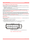
Figure 1-1. HMS-318 List 3 Shelf - Front View ................................................................... 1-2
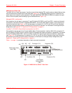
Figure 1-2. HMS-318 List 3 Shelf - Rear View .................................................................... 1-3
Figure 1-3. Input Power Terminal Block (TB1) .................................................................... 1-5
Figure 1-4. Alarms Wire-Wrap Field (TB2) ......................................................................... 1-6
Figure 1-5. HLU Slot Wire-wrap Pinouts for HDSL Circuits ................................................ 1-9
Figure 1-6. HLU Slot Wire-wrap Pinouts for HDSL2 Circuits .............................................. 1-9
Figure 1-7. HLU Slot Wire-wrap Pinouts for HDSL4 Circuits ............................................ 1-10
Figure 1-8. HLU Slot Wire-wrap Pinouts for Span Powered xDSL ................................... 1-11
Figure 1-9. HMS-318 List 3 Shelf RS-232/X.25 Remote Management Ports .................. 1-12
Figure 1-10.Multishelf Network Ports ................................................................................. 1-13
Figure 1-11.Central Office Equipment Rack Configuration ................................................ 1-14
Figure 2-1. Grounding Lug ................................................................................................ 2-10
Figure 2-2. Input Power Terminal Block (TB1) .................................................................. 2-11
Figure 2-3. Alarms Wire-wrap Field (TB2) ........................................................................ 2-12