


December 20, 2004 Chapter 2: Installation
LTPH-UM-1261-01 2-7
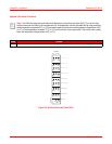
Rack Mounting Procedure
To secure the HMS-318 List 3 shelf to the telco-style rack, you must use the mounting screws provided or follow
your local practices for installing the shelves into your telco-style equipment rack. Ensure that the adapter brackets
have been securely fastened [see “Adapter Bracket Mounting Procedure (19-inch Telco-style Equipment Rack)” on
page 2-5, “Adapter Bracket Mounting Procedure (23-inch Telco-style Equipment Rack)” on page 2-5, or “Adapter
Bracket Mounting Procedure (ETSI-style Equipment Rack)” on page 2-6 for more information].
Perform the following procedure to mount the HMS-318 List 3 shelf into a telco-style equipment rack.
DSX-1 AND HDSLX CONNECTIONS
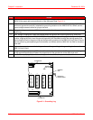
Perform the following procedure to connect the DSX-1 and HDSLx interface cables to connectors P1, P2, P3 and P4
(see Figure 1-2 on page 1-3 for connector location and “Connecting to HDSL, HDSL2, and HDSL4 Circuits” on
page 1-8, for connector descriptions).
!
IMPORTANT
To prevent injury, review the “Safety Guidelines” on page xi and the “Special Rack-Mounting
Precautions” on page 2-4 before installing the HMS-318 List 3 shelf in the telco-style equipment
rack.
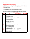
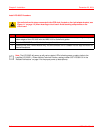
Step Action
1 Locate the telco-style equipment rack position you plan to install the HMS-318 List 3 shelf into.
2 Verify that there are no obstructions and ensure that the telco-style equipment rack is stabilized.
3 Position the shelf in the telco-style equipment rack lining up the bracket holes on the shelf with the holes
on the rack and secure with the four #12-24 x .375 inch mounting screws (see Table 2-1 on page 2-2).
4 Tighten the screws using a 1/4-inch flat-blade screwdriver.
5 You are now ready to begin interconnecting the communications cables that apply to your application
(see “DSX-1 and HDSLx Connections” on page 2-7 or “Span Powered xDSL Connections” on page 2-8).
DANGER
Before making both DSX-1 and HDSLx connections to the HMS-318 List 3 shelf, ensure that the
Main CO power breaker is off. Otherwise, severe injury to the installer or damage to the unit may
result.
Note: The vertical spacing for EIA racks is 1.75 inches (4.44 cm), with mounting holes
spaced 1.5 inches (3.81 cm) apart. Vertical spacing for WECO racks is 2.0 inches (5.08 cm),
with mounting holes spaced 1.0 inch (2.54) apart.