


December 20, 2004 Chapter 1: Product Description
LTPH-UM-1261-01 1-13
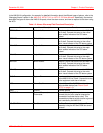
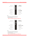
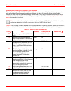
Table 1-4. J27 – AUX RS-232 Management Port (DTE)
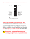
ETHERNET REMOTE MANAGEMENT PORTS
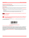
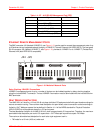
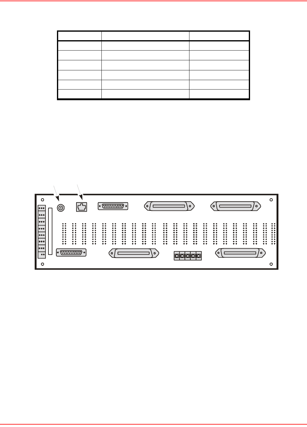
The BNC connector J24 (labeled 10 BASE-2), see Figure 1-10, can be used to connect the management ports of up
to 32 shelves into an integrated network through a 10 BASE-2 (Thinnet) Ethernet LAN (IEEE.802.3). The rear-panel
RJ-45 connector J25 (labeled 10 BASE-T), see Figure 1-10, provides a 10 BASE-2 or a 10 BASE-T (Twisted-Pair)
Ethernet LAN (both IEEE.802.3 compatible).
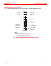
Figure 1-10. Multishelf Network Ports
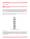
Daisy-Chaining 10BASE-2 Connections
10BASE-2 management ports of up to x number of shelves can be hubbed together by daisy-chaining together
using the included BNC-T connector. The last 10BASE-2 connection must be terminated with the included 50 ohm
BNC terminator.
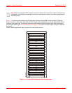
HEAT DISSIPATION FACTORS
The HMS-318 List 3 shelf is a 12-inch (30.48 cm) deep individual CO equipment shelf with open-faced mountings for
natural convection cooling. The maximum heat dissipation for open-faced, natural convection-cooled mountings is
limited to 134.7 Watts per square foot as defined in Section 4.1.4 of the NEBS standard for Physical Protection
(GR-63-CORE) for all equipment placed in a CO environment.
The heat dissipation footprint of an HMS-318 List 3 shelf is approximately 5.9 square feet. Therefore, the maximum
permissible heat dissipation per rack is 5.9 square feet x 134.7 Watts per square foot equals 790 Watts.
The maximum allowable heat dissipation for each telco-style equipment rack is:
• 790 watts for a 19-inch (48.3-cm) wide rack
Pin No. Signal Direction
1Shield —
2 Transmit Data (TD) Out
3 Receive Data (RD) In
6 Data Set Ready (DSR) In
7 Ground (GND) —
20 Data Terminal Ready (DTR) Out
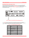
J24 J25
OS RS232 PORT
CO PAIR 2
AUX RS232 DTE PO RT
SPAN PAIR 2
14-1261R1
10 BASE-T
10 BASE-2
12345
CO PAIR 1
-48VA -48VB BAT RTN
FGND
FUSEFUSE
PINS 3 & 4
MUST BE BRIDGED
15 A MAX 15 A MA X
25
25
25
1
1
1
26
26
26
SPAN PAIR 1
25 1
26
50
50
50
50