


Chapter 2: Installation December 20, 2004
2-14 LTPH-UM-1261-01
Install LPS-300C Procedure
ATTENTION
Use anti-static wrist-straps connected to the ESD Jack (located on the right adapter bracket, see
Figure 1-1 on page 1-2) when inserting a circuit card. Avoid touching components on the
circuit card.
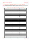
Step Action
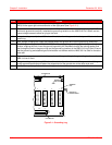
1 Hold the LPS-300C Power Module vertically with the front of the circuit card toward you. Align the top and
bottom edges of the LPS-300C with the HMS-318 List 3 shelf slot guides.
2 Slide the LPS-300C Power Module into its respective slot.
3 Press the LPS-300C Power Module firmly into the connector until it is seated into the edge-connector on
the shelf backplane.
Note: The LPS-300C will power up with various status LEDs indicating power up status (refer to the
LoopStar LPS-300C L1 Power Module Technical Practice, catalog number SCP-LPS300-010 in the
“Related Publications” on page iii for the proper power up descriptions).