


December 20, 2004 Chapter 1: Product Description
LTPH-UM-1261-01 1-11
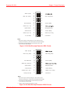
Wire Wrap Connections – Span Powered xDSL
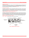
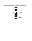
Figure 1-8 shows the LPS-300C slot pinouts on the HMS-318 List 3 shelf rear panel for xDSL circuits.
Figure 1-8. HLU Slot Wire-wrap Pinouts for Span Powered xDSL
xDSL A IN
xDSL B IN
A
B
C
D
E
F
J
H
Ground (GND)
xDSL A OUT
xDSL B OUT
Management Bus *
Frame Ground -48 Vdc Battery
Fuse Alarm **
1
2
3
4
5
6
7
8
9
10
K
L
**
Fuse alarm normally floating (0 to -80 Vdc maximum)
and at -48Vdc (10 ma maximum) when activated.
*
System alarm and management bus reserved.
Notes:
xDSL A IN
xDSL B IN