


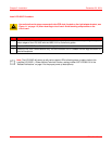

Chapter 2: Installation December 20, 2004
2-10 LTPH-UM-1261-01
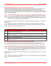
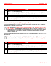
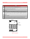
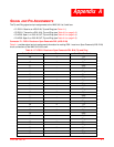
Figure 2-1. Grounding Lug
Step Action
1 Looking at the HMS-318 List 3 rear panel, find the ground lug location (labeled BONDING WIRE MIN #10
AWG) on the upper right corner extension of the right panel (see Figure 2-1).
2 Measure between the telco-style rack and the HMS-318 List 3 Shelf the correct length of a #10 AWG
(minimum) ground wire so that it reaches the ground lug location on the HMS-318 List 3 Shelf, and cut.
Leave enough excess to allow for tying to the rack.
3 Using wire strippers, strip about 5/8 inches of insulation from the ground wire that you will fasten to the
ground lug.
4 Next, using a crimping tool, insert the stripped end of the ground wire into the ground lug, and crimp.
5 Attach the ground lug to the HMS-318 List 3 Shelf by placing the ground lug against the ground lug
location, aligning the hole. Insert the ground-lug screw (#12 Hexhead) through the locking washer and
then through the hole in the ground lug and the ground lug location on the HMS-318 List 3 Shelf. Ensure
that the ground lug and attached ground wire does not interfere with the HMS-318 List Shelf or the telco-
style rack.
6 Tighten the screws to secure the locking washer and the ground lug to the ground lug location on the
HMS-318 List 3 Shelf.
7 Using wire strippers, strip about 5/8 inches of insulation from the other end of the ground wire. Using
locally approved practices and fasten the stripped end of the ground wire to the telco-style rack.
8 Use the tie-wraps (supplied) and secure the ground wire to the rack to prevent rotation.
BONDING WIRE
MIN #10 AWG
GROUND LUG
HEXHEAD SCREW
WIREWRAP
PINS
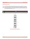
17-1261R1
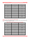
P4
SHIELD
GND
A
B
C
D
E
F
H
L
J
K
1
2
3
4
5
6
7
10
8
9
A
B
C
D
E
F
H
L
J
K
1
2
3
4
5
6
7
10
8
9
12
A
B
C
D
E
F
H
L
J
K
1
2
3
4
5
6
7
10
8
9
3
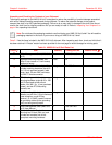
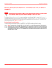
P2 CONNECTOR
P4 CONNECTOR
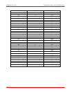
A
B
C
D
E
F
H
L
J
K
1
2
3
4
5
6
7
10
8
9
4
P2
SHIELD
GND
P4
25
25