


Chapter 1: Product Description December 20, 2004
1-14 LTPH-UM-1261-01
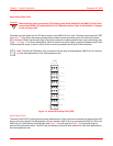
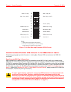
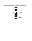
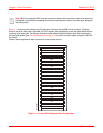
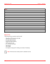
Figure 1-11 shows a typical example of a CO equipment rack layout using HMS-318 List 3 shelves. The figure
shows a rack with a fuse panel, eight HMS-318 List 3 shelves, each separated by a two rack space baffle with the
remaining shelf space open. As the figure illustrates, baffles should be placed between each shelf to reduce the
chimney heating effect (see “Air Flow Guidelines” on page 1-15 for further information about cooling the HMS-318
List 3 shelf).
Outdoor cabinet applications require forced air to ensure proper cooling.
Figure 1-11. Central Office Equipment Rack Configuration
Note: Refer to the respective ADC card user manuals to determine the maximum number of cards that can
be installed in a shelf before exceeding the maximum heat dissipation density of the telco-style equipment
rack configuration.
Fuse Panel
Shelf
Baffle
16A-1261R1
Shelf
Baffle
Shelf
Baffle
Shelf
Baffle
Shelf
Baffle
Shelf
Baffle
Shelf
Baffle
Shelf
Baffle