


December 20, 2004 Chapter 2: Installation
LTPH-UM-1261-01 2-9
BONDING (SAFETY) GROUND, POWER AND FRAME GROUND, ALARM, AND OPTIONAL
F
AN INPUTS
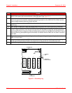
Bonding (safety) ground, power and frame ground, and alarm connections and cabling are marked for ease of
installation [see ground lug location (labeled BONDING WIRE MIN #10 AWG)], TB1, and TB2 on the rear panel of
the HMS-318 List 3 Shelf, and the following procedures for proper safety ground, power, alarm, and optional fan
(alarms) connections (see Figure 1-2 on page 1-3).
Bonding (Safety) Ground Procedure
To connect the Bonding (Safety) ground to the HMS-318 List 3 Shelf, complete the following steps:
!
IMPORTANT
Before making connections to the HMS-318 List 3 shelf, ensure that the Main CO power breaker
is off. Otherwise, severe injury to the installer or damage to the unit may result.
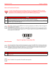
Note: The ground wire exiting the HMS-318 List 3 Shelf is terminated with a ground lug. The lug can be
either a one-hole or two-hole lug. The surface of the lug that connects to the HMS-318 List 3 Shelf should
be cleaned with an antioxidant. The same should also be applied to the surface of the telco-style rack where
the connection is to be made. The #12 Hexhead screw (supplied) is used to connect the grounding lug to
the HMS-318 List 3 Shelf.