


December 20, 2004 Chapter 2: Installation
LTPH-UM-1261-01 2-11
Power and Frame Ground Procedure
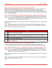
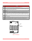
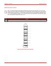
Figure 2-2. Input Power Terminal Block (TB1)
Alarms Procedure
!
IMPORTANT
To avoid voltage differences from building up between the shelf ground (GND) bus and the
ground pins of the management terminal that connects to the RS-232 ports, connect the shelf
ground pins and the terminal ground bus to the TB1 FGND (frame ground) pin.
Step Action
1 Use locally approved practices to connect #12 AWG (minimum) power wiring from -48Vdc Office Battery
to -48VA and -48VB terminals on TB1-1 and TB1-2 (see <Cross-Ref>Figure 2).
2 Connect #12 AWG (minimum) power wiring from the Battery Returns to BAT RTN terminals on TB1-3
and TB1-4 (see <Cross-Ref>Figure 2).
Note: Slots 1 through 11 on the HMS-318 List 3 shelf are powered by the -48VA bus. Slots 12 through 22
are powered by the -48VB bus.
In the HMU/HLU configuration, the HMU-319 is diode-OR’ed to both power busses to guard against power
failure in the event that one power supply is lost. This feature requires the two ground (GND) terminals to
be connected on the HMU card.
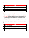
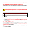
Note: As described in “Power and Alarm Connections” on page 7, the HMS-318 List 3 shelf provides alarm
outputs in the form of an Alarms wire-wrap field. This field consists of a three-pin wire-wrap header for alarm
management. Before connecting the alarm inputs, you must first determine whether the external alarm
equipment requires either an NO or an NC circuit to pass an alarm.
Step Action
1 Use locally approved practices to connect the alarm inputs to the Alarms wire-wrap field (see Figure 2-3
on page 2-12).
Note: The HMU-319 is required for NO and NC alarm operation.
-48VA
FUSE
1234
5
-48VB
FUSE
BAT RTN
FGND
TB1
1
5
A MAX 1
5
A MAX
3
/
16-1261R1