


SmartView XPro Installation and Use Page 40
4. Using the SmartView XPro
This section explains the general operation of the SmartView XPro. We recommend
that you read this section before starting to use the product.
4.1 Rear panel special function switches
Before powering on the SmartView ensure that the two option switches on the rear
are set to the OFF (up) position. Option switch 1 is reserved for future use and
option switch 2 is used to enable firmware upgrades (see section 6).
4.2 Power supply connections and indicators
The SmartView XPro is fitted with two power inlets that are labelled A and B (see
figure 2). These power inlets are both the same and either inlet may be used to
power the SmartView XPro. The SmartView is shipped with a single power adapter
but you may optionally purchase a second power adapter to provide power supply
redundancy (part code PSU-IEC-5VDC). Plug the power adapter into one of the
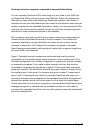
inlets. The power indicators on the front of the SmartView (see figure 1) monitor the
voltage that is being supplied to each power inlet. If the power indicators A or B are
illuminated then a healthy power adapter is connected. If you have two healthy
power adapters connected then you may disconnect and reconnect one of then
without disturbing the operation of the SmartView.
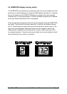
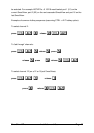
4.3 USER display and key switch
The USER key selects the user port that is shown on the green USER display (see
figure 1). Pressing the key will cause the green display to change to the next user
port in numerical sequence. When the USER display is changed, the red
COMPUTER display will also change to show the current connection status of the
new user port. SmartView 4XPro models have 4 user ports and SmartView 2XPro
models have 2 user ports.