


10 64179008APL1-5A
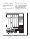
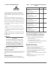
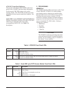
ATM BCU Front Panel Indicators
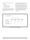
The network LED labeled NETWORK on the front
panel of the ATM BCU provides status information
for the network DS1 IMA using a color-coded
message format. The TEST LED provides test status
information for the network and access modules. See
Table 4.
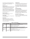
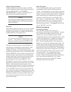
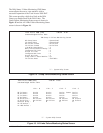
Quad ADSL Access Module Front Panel Indicators
After the initialization sequence, the status of the each
ADSL loop is reflected by the color of the
corresponding LOOP LED. See Table 5 for
descriptions.
3. PROVISIONING
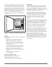
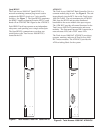
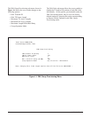
ADMIN Port
The ADMIN interface (DB-9 connector) on the Total
Access 1000 DAT ATM BCU is used to change
provisioning options, obtain access module status
through menu screens, and initiate tests on circuits.
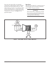
To access the menu screens, connect a VT100
terminal or computer running a terminal emulation
program to the craft interface port using a standard
male-to-female RS-232, DB-9 cable. Craft port
settings are as follows:
• 9600 Baud
• No parity
• 8 Data bits
• 1 Stop bit
CAUTION
The ATM BCU retains provisioning setup when
removed from the chassis. If inserted into another
chassis, the provisioning setup is invoked on
that chassis’ access modules.
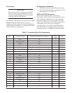
Table 4. ATM BCU Front Panel LEDs
Table 5. Quad ADSL plus POTS Access Module Front Panel LEDs
DELnoitacidnInoitpircseD
krowteNneerG
deR
ffO
pUsipuorgAMI
nwoDsipuorgAMI
eruliaferawdrahrorewopoN
tseTneerG
ffO
eludomotdeilppasirewopnehwneergeblliwtub,desunuyltnerrucsiDELsihT
eruliaferawdrahrorewopoN
DELnoitacidnInoitpircseD
4-1pooLneerG
neerGgnihsalF
deR
wolleY
ffO
pUpooL
gniniartpooL
puniartotgnitpmettaton,nwoDpooL
tsetnipooL
dengissanU-ecivreSfotuO