


64179008APL1-5A 7
C A U T I O N !
SUBJECT TO ELECTROSTATIC DAMAGE
OR DECREASE IN RELIABILITY.
HANDLING PRECAUTIONS REQUIRED.
2. INSTALLATION/OPERATION
After unpacking the unit, inspect it for damage. If
damage is noted, file a claim with the carrier, then
contact ADTRAN. Refer to Warranty and Customer
Service.
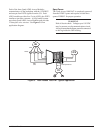
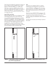
The Total Access 1000 DAT can be wall, pole, or
pedestal mounted. Templates are provided with each
system to support accurate mounting of the enclosure.
The Total Access 1000 DAT complies with Part 15 of
the FCC rules. Operation is subject to the following
two conditions:
1. This device may not cause harmful interference,
and
2. This device must accept any interference received,
including interference that may cause undesired
operation.
Changes or modifications not expressly approved by
ADTRAN could void the user’s authority to operate
this equipment.
Compliance
CAUTION
Per GR-1089-CORE October 2002, Section 9,
the Total Access 1000 system is designed and
intended only for installation in a DC-C
(common) Bonding and Grounding system. It is
not intended or designed for installation in a
DC-I (isolated) Bonding and Grounding system.
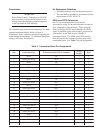
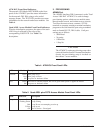
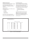
See Table 1 for Compliance Codes.
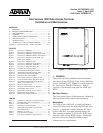
Required Clearances
A minimum 18 inches of clearance is required in front
of the chassis to allow for opening of the enclosure
door.
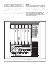
Mounting Brackets
The Total Access 1000 DAT enclosure contains
brackets that support wall, pole, or pedestal mounting.
Tools Needed (Wall Mount or Polemount)
The Total Access 1000 DAT Chassis mounts and
connects with standard fasteners and hand tools:
• Six #6 x 3/4-inch, flat-head wood screws.
• Drill and drill bit set.
• Flat-head screwdriver (medium).
• Two Phillips-head screw drivers (small /medium)
• Selected punch-down block and tool.
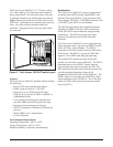
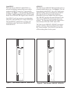
Mounting The Enclosure
Install the enclosure as follows:
1. Position the mounting template at the desired
location, observe required clearances.
2. Ensure the mounting template is plumb then mark
through the template holes to identify where the
pilot holes will be drilled.
3. Using a 1/16-inch bit, drill pilot holes at the marked
locations.
4. Mount the chassis using the six #6 by 3/4-inch
flat-head wood screws.
Table 1. Total Access 1000 DAT Compliance
Codes
edoCtupnItuptuO
)sissahC(
)CP(edoCrewoP
)CT(edoCnoitacinummoceleT
)CI(edoCnoitallatsnI
C
X
E
C
X
–
)USP(
)CP(edoCrewoP
)CT(edoCnoitacinummoceleT
)CI(edoCnoitallatsnI
C
X
A
C
–
–
)UIL2H(
)CP(edoCrewoP
)CT(edoCnoitacinummoceleT
)CI(edoCnoitallatsnI
C
X
A
C
–
–
)STOPsulpLSDA(
)CP(edoCrewoP
)CT(edoCnoitacinummoceleT
)CI(edoCnoitallatsnI
C
–
E
C
X
–
)UCBMTA(
)CP(edoCrewoP
)CT(edoCnoitacinummoceleT
)CI(edoCnoitallatsnI
C
–
A
C
–
–