


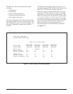
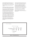


A-164179008APL1-5A
WARNING
Risk of electric shock. Voltages up to 190 VDC
may be present on telecommunications circuit.
Always ensure that the frame ground is connected
to the lug inside the OSP housing.
Required Clearances
A minimum 18 inches of clearance is required in front
of the chassis to allow for opening of the enclosure
door.
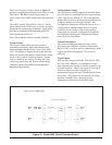
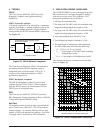
Mounting Brackets
The Total Access 1000 DAT enclosure contains
brackets that support wall, pole, or pedestal mounting.
Tools Needed (Wall Mount or Polemount)
The Total Access 1000 DAT Chassis mounts and
connects with standard fasteners and hand tools:
• Six #6 x 3/4-inch, flat-head wood screws.
• Drill and drill bit set.
• Flat-head screwdriver (medium).
• Two Phillips-head screw drivers
(small /medium)
• Selected punch-down block and tool.
• Mounting template (included).
INSTALLATION
After unpacking the unit, inspect it for damage. If
damage is noted, file a claim with the carrier, then
contact ADTRAN. See Warranty and Customer
Service.
1. Mount the Enclosure
Install the enclosure as follows:
• Position the mounting template at the desired
location, observe required clearances.
• Ensure the mounting template is plumb then
mark through the template holes to identify
where the pilot holes will be drilled.
• Using a 1/16-inch bit, drill pilot holes at the
marked locations.
• Mount the chassis using the six #6 by 3/4-inch
flat-head wood screws.
Appendix A
Quick Start Guide – ADSL plus POTS
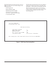
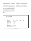
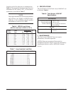
2. Make the HDSL2 Connections
Connect three or four HDSL2 pairs to the Total
Access 1000 DAT as follows:
• Locate the gel filled connectors beneath the
modules (there are five of these).
• Use Figure 4 to determine which connectors are
for which loop.
• Locate the two empty holes, labeled T and R, at
the base of one of the connectors.
• Using a large flat-head screwdriver, loosen the
bolt at the top of the connector.
• Insert one wire of the HDSL2 pair into the hole
labeled T and one into the hole labeled R. Make
sure that the wires are all the way in.
• Tighten the bolt at the top of the connector.
• Repeat the preceding instructions for the
remaining HDSL2 pairs.
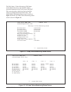
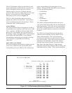
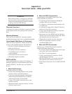
3. Make the POTS Connections
Connect up to 12 POTS lines from the network
using the following instructions:
• Locate the 25 pair termination block on the right
side of the Total Access 1000 DAT.
• See Table 2 for pin assignments.
• Using a small flat-head screwdriver, lift the
appropriate pair connector.
• Insert the POTS pair, one wire into each hole,
then push the pair connector all the way in.
• Repeat these instructions for all additional POTS
inputs.