


114 Operation and Maintenance Manual
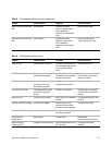
Low Response Contaminated ceramic
tubes.
If there does not appear to
be a leak, then the tubes
should be inspected.
Contamination can result
from column bleed, samples
which may contain volatile
metal complexes, and large
injections of coke forming
hydrocarbons.
Replace tubes.
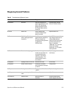
Wandering Baseline Poor temperature control. Monitor the temperature on
the Controller. It should vary
by no more than ±5
°
C.
Check for a loose connection
on the heating element or
thermocouple. Reposition
the thermocouple in the
Burner.
Wandering Baseline Contamination in one of the
Detector gases.
Check the difference in the
output signal between ozone
on and off. The difference
should be between 0.2-2 mV
after equilibration.
Change Detector gases after
adding in-line traps.
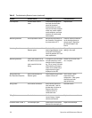
Wandering Baseline Leak in the oxidizer line at
the oxidizer inlet connection.
Leak at weld of H
2
inlet
fitting.
If using SCD, use a microliter
syringe containing a small
amount of sulfur compound
e.g., CS
2
to “snoop” for leaks
while watching mV output.
Leaks are very evident by a
large increase in signal
displayed on the LED.
Reseat air line into air inlet
nut, or replace.
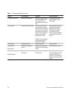
Tailing Peaks with
Non-Equimolar Response
Severe contamination of
Detector gases.
High background signal with
respect to ozone off.
Avoid “house” gases,
especially air from
compressors. Clean gases
should be used with
appropriate traps.
Tailing Peaks Poor column connection. Verify column position at
inlet and outlet. Look for
discoloration of column at
Detector side which
indicates column in
combustion zone.
Reinstall column.
Tailing Peaks Cracked tubes. Confirm pressure and
vacuum ranges. Inspect
columns and ferrules.
Replace tubes as needed.
Controller Reads >1000 °C Thermocouple open. Check electrical resistance
between thermocouple pins.
Replace thermocouple.
Table 5 Troubleshooting Detector Issues (continued)
Problem Possible Cause Diagnosis Corrective Action