


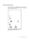
52 Operation and Maintenance Manual
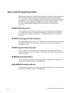
• To select no gas ballast flow (not recommended), turn the restrictor
plate so that none of the indentations are aligned with the indentation
on the side of the oil return assembly.
• To select low gas ballast flow, turn the restrictor plate so that the single
indentation on the restrictor plate is aligned with the indentation on the
side of the oil return assembly.
• To select high gas ballast flow (the setting the ballast control is shipped
from the factory), turn the restrictor plate so that the two indentations
are aligned with the indentation on the side of the oil return assembly.
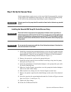
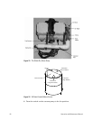
Installing the Welch Dry Piston Vacuum Pump
The Welch Dry Piston Pump may be used as a direct replacement for an
oil-sealed vacuum pump for the NCD or SCD. This pump produces all the
advantages of an oil-free pump with little or no loss in instrument
performance, however, operating Detector and Burner pressures will typically
be a few Torr higher than those obtained with the oil-sealed pump.
To install the dry piston vacuum pump, follow these steps:
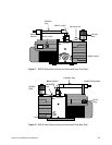
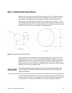
1 Remove the pump from its packaging and place on an accessible work
surface with the power cord side nearest to you and the pump "INLET" port
to your right. Refer to Figure 15 as a visual aid to these instructions.
2 Verify that the voltage of the pump matches that of the Detector.
3 Open the plastic bag containing the Dry Piston Pump Kit. Locate the brass
elbow and brass barb (3/8" NPT). Remove their plastic protective caps and
wrap three or four turns of Teflon tape (not supplied) onto the threaded
connections. Screw the barb fitting into the elbow and tighten using
wrenches. Similarly, remove the plastic cap from the pump's inlet fitting
and screw elbow into it. Tighten the elbow so that the barb ends up pointed
parallel to the floor and pointed toward the power cord side of the pump.
4 Locate the mounting brackets, 4 small screws and washers and spring clips.
Use 2 screws and washers to attach the spring clips, one to each bracket.
5 Using the supplied Torx wrench, remove two Torx screws from the pump,
the right corner screw located closest to you and the closest screw to you
located immediately to the left of the pump's handle.
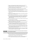
6 Attach the brackets to these locations using the Torx screws as showing in
Figure 15.
7 Attach the short piece of ½" ID hose tubing supplied in the Dry Piston
Pump Kit to the brass barb and use one of the supplied hose clamps to
tighten it onto the barb.
8 Place a second hose clamp over the other end of the plastic tube. Insert the
barb on the elbow end of a Chemical Trap into the open end of the short
plastic hose that was just attached to the brass barb on the pump.
9 Rotate the Chemical Trap so that it is retained by the spring clips.