


Operation and Maintenance Manual 59
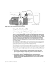
Step 7: Install the Dual Plasma Burner
Remove the cover plates from the Detector area of the GC to expose the hole
into the oven through which a Detector is normally mounted. If the GC has
more than one available Detector position, pick the most convenient one.
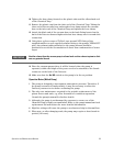
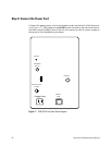
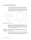
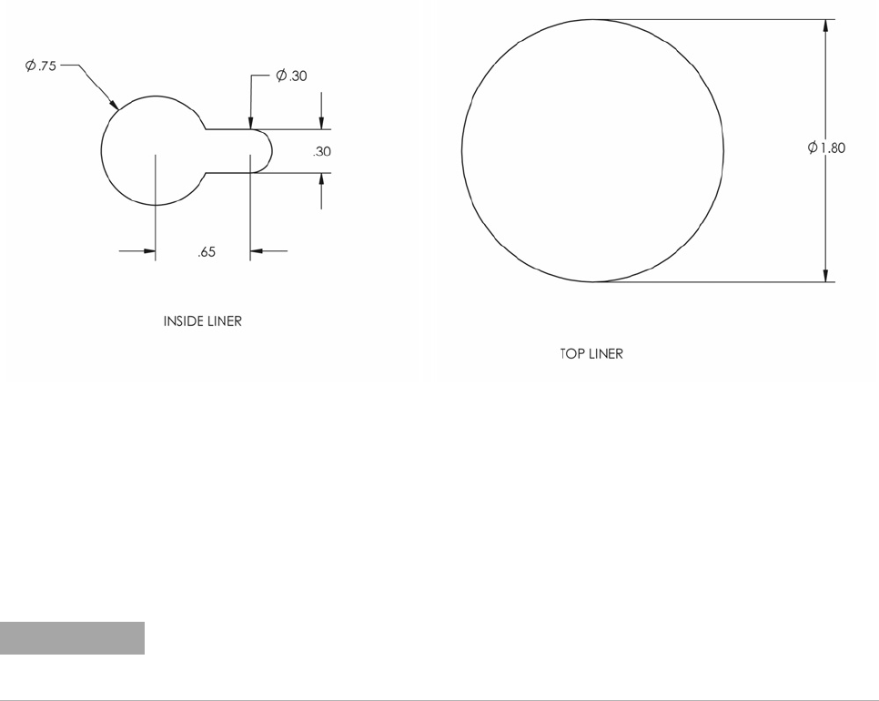
Prepare the GC by cutting the inside liner and top liner per Figure 17. Note
that mounting fastener patterns will vary by GC manufacturer. Make sure the
notch in the inside liner is on the right, in order to accommodate the geometry
of the Burner as it sits in the shroud and mounting plate.
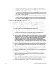
Align the Burner mounting plate with the mounting screw holes on the GC.
Clear the hole into the GC oven of interfering insulation, and then secure the
mounting plate onto the oven with the screws provided. Attach the Burner's
heated base connector to the GC's temperature control circuit. Consult your
GC's operation or service manual to confirm proper connection of the 100 ohm
RTD sensor and the cartridge heaters.
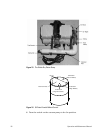
Position the Dual Plasma Burner (column end down) into the tapered fitting of
the heated base, with the lower hydrogen line and pin aligned with the slot in
the heated base. The Burner should be secure when properly positioned.
Figure 18 Dimensions of GC Liner Cut-Outs
NOTE
Occasionally geometric design changes will occur within or between GC models. If the
mounting plate provided does not match up with the top of the GC, contact Agilent for
additional information.