


Operation and Maintenance Manual 47
11
Remove the drain plug and the bonded seal from the oil mist filter. The
bonded seal looks like a metal washer with a black inner o-ring.
12 Install the bonded seal to the oil mist filter drain adapter. The drain adapter
looks like a drain plug with a small plastic nozzle.
13 Screw the black drain adapter and bonded seal into the oil mist filter.
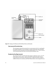
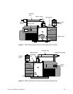
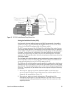
14 Remove the plastic protective cover from the pump exhaust port. Place the
centering o-ring on the pump exhaust port (see Figure 13).
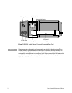
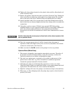
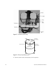
15 Place the oil mist filter onto the o-ring on the pump exhaust port. Install the
filter so that the gray half is above the white half of the filter (see Figure 11
and Figure 12).
16 Position the oil mist filter so the drain adapter points toward the gas ballast
inlet (see Figure 11 and Figure 12).
17 Fit the clamping ring onto the adapter and oil mist filter and hand tighten.
18 Turn the gray plastic gas ballast knob counterclockwise to position II. Press
the knob down against the spring and continue to turn counterclockwise
until the knob is free. Remove knob from the pump. Confirm that the
spring is still in place.
19 Locate the tall aluminum gas ballast control assembly, and install the small
o-ring into the groove on the shaft.
20 Insert the gas ballast control assembly into the pump, pressing down
against the spring, and turn it clockwise until the nozzle on the assembly is
directly over the mark on the top of the pump.
21 Cut approximately 3/4 of the black silicone oil return line and insert the
steel restrictor approximately half-way into the line. If needed, use a small
screwdriver or other small tool to aid in positioning the restrictor.
22 Fit one end of the oil return line to the drain adapter on the oil mist filter.
Fit the other end of the line to the nozzle on the gas ballast adapter. Ensure
that the tubing is not tight and has no tight bends. Secure the line at each
end, using the black hose clips provided.
23 Add oil to the pump via either of the two oil fill caps. The oil level should be
between one-third and one-half when viewed in the oil sight glass. Replace
the oil fill cap prior to operation of the pump.
24 Place a hose clamp over the black heat shrink end of the 6’ Tygon vacuum
hose, and connect the hose to the barbed fitting labeled Exhaust on the
back of the Detector. Tighten the hose clamp securely.
25 The SCD should be placed near the GC and be accessible from the rear in
order to connect the electrical power and the recorder signal cable.
WARNING
Do not operate the vacuum pump with the oil level below the minimum oil level mark or
above the maximum oil level mark.