


58 Operation and Maintenance Manual
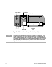
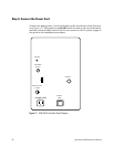
Step 6: Install the Signal Output Cables
Signal output cables are available from Agilent as standard equipment and can
be used with most data systems. Confirm that the output cable supplied is
correct for your system. A standard cable fitted with two crimp lug connectors
is supplied for use with most integrators, recorders or data systems. Attach
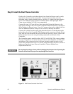
the BNC connector end of the recorder cable to the matching output
connector, labeled RECORDER OUTPUT, on the back of the SCD (see
Figure 17).
Standard Cable Connection
The standard recorder cable is connected to the integrator by installing the
red crimp-lug connector to the signal terminal (+) and the black crimp-lug
connector to the negative terminal (-). No additional ground connection is
required.
HP 3390 Series Integrator Cable Connection
The keyed-edge connector on the HP 3390 series cable is attached to the signal
input of HP 3390 series integrators. Note that the connector can only be
installed one way.
HP 3396 Integrator Cable Connection
The jack plug on the HP 3396 cable is attached to the analog signal input
connector at the rear of the integrator. This cable also works with the Agilent
35900 controller.
HP 5890 GC Analog Input Board
A cable made specifically for this input board is available. This board is used
when the SCD signal is input to ChemStation.
Agilent 6890 GC Analog Input Board
A cable made specifically for this input board is available. This board is used
when the SCD signal is input to ChemStation.