


Operation and Maintenance Manual 51
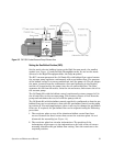
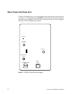
Setting the Gas Ballast Position (RV5)
Set the mode selector halfway between the High Vacuum mode, the small 6
symbol (see Figure 14) and the High Throughput mode. Do not set the mode
selector to the High Throughput mode, the large
6 symbol.
The RV5 vacuum pump and the Oil Drain Kit with ballast flow control ensure
the vacuum pump operates continuously with a gas ballast flow. The purpose
of the ballast control is to sweep ambient air into the pump oil. The air purges
the water (created from the combustion of air and hydrogen in the Burner)
and the oil (vaporized by the pump) into the oil coalescing filter. The filter
separates the oil from the water, vents the air and water, and returns the oil to
the vacuum pump.
The Oil Drain Kit with the ballast control continuously returns trapped oil in
the oil mist filter to the vacuum pump. This feature reduces oil loss from the
pump and minimizes the need to refill the pump with oil.
The Oil Drain Kit with the ballast control supplied is configured so that the gas
ballast flow rate is equivalent to that with the gas ballast control on the pump
in position II. For most applications, there is no need to change the gas ballast
flow rate. If required, the gas ballast flow can be adjusted using the following
procedure.
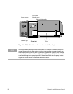
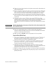
1 The restrictor plate on top of the aluminum ballast control has three
screws. Remove the three screws that secure the restrictor plate. Do not
dismantle the assembly (see Figure 16).
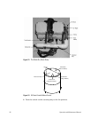
2 The restrictor plate has circular indentations. The position of the
indentations with respect to the indentation on the side of the oil return
assembly identifies the gas ballast flow setting. Turn the restrictor to the
required position:
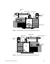
Figure 14 RV-5 Oil-S ealed Vacuum Pump Exhaust Line