


60 Operation and Maintenance Manual
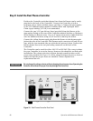
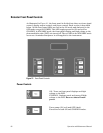
Step 8: Install the Dual Plasma Controller
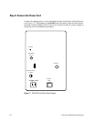
Position the Controller such that the gas lines from the Burner can be easily
attached to the back of the Controller. Connect the Controller to both a
hydrogen source and an oxidant source, per Step 1. Connect the gas supplies
to the 1/8" bulkhead unions marked "Oxidizer Inlet" and "Hydrogen Inlet."
Clean copper tubing (1/8" OD) is recommended.
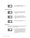
Connect the two 1/16" gas delivery lines (provided) from the Burner to the
appropriate fitting on the rear of the Controller marked Oxidizer or Hydrogen
in the Outlets (to Burner) area. Use a 1/4" open-end wrench to tighten the nut
onto the bulkhead unions, using a 9/16" wrench to back-up the union.
Connect the yellow thermocouple plug from the Burner to the thermocouple
jack at the rear of the Controller. The thermocouple connector will only fit one
way, with the iron terminal (the one with the two grooves) down. Connect the
Burner heater line to the two pin locking connector on the back of the
Controller.
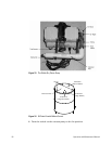
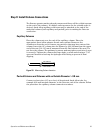
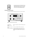
The Controller can be used for either 100/115 or 230 VAC. The correct voltage
for your Controller is set at the factory; however, this should be verified upon
installation. The voltage selection is shown through a small window on the
power entry module (see Figure 19). If the voltage setting is incorrect, check to
make sure that the proper fuses are installed. Contact Agilent for a
replacement fuse set.
WARNING
Do not change the voltage selector without changing the main power fuse. Operating the
Controller box without the proper fuse may damage the electronics.
Figure 19 Dual Plasma Controller Rear Panel