


68 Operation and Maintenance Manual
Reaction cell pressure, with air to ozone
generator OFF (0 psi setting on internal
regulator) and transfer line capped: ___________________ torr
Tighten connections if necessary and check to make sure pressure stabilizes in
the expected region. If proper pressure is not obtained contact Agilent for
assistance. If the reaction cell pressure is within the expected range, record
the value, reset the internal air regulator to 3-6 psi, turn the pump OFF and
proceed with the recorder test.
Recorder Test
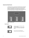
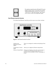
The standard 355 SCD and 255 NCD recorder output configuration is 1 volt full
scale. In addition, an output range can be set with the recorder output
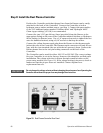
selection switch located on the back panel (Figure 11). Use a small
screwdriver to adjust the switch to the proper position for your integrator or
data system.
To check that the recorder cable has been properly connected to the integrator
or data system, set the integrator to a high sensitivity setting (e.g. attenuation
of x 1) and plot the background signal. Use the Output Offset to decrease the
Detector baseline. If the recorder cable is connected correctly, the baseline will
shift in response to changes in the Output Offset. If the polarity of the
connection is incorrect, a negative response will be observed when the
baseline is increased, and vice versa. Switch the polarity of the wires to
correct this problem. If no response is observed, re-check the signal
connections and repeat the test. Contact Agilent if there is no data system
response after completion of this test.