


12 Introduction WAVE 2-Way Wireless Accessories and Adapters for Touch Panels
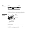
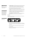
• Empty/Full gauge—The BATTERY indicator gauge (empty-full) provides a
visual indication of the charge level of the battery currently being used. If
the battery's charge is high, all left-to-right indicator lamps will be lit.
• Test—Pressing the TEST button displays an indication of the current bat-
tery's charge level on the front panel’s Empty/Full gauge.
• Charging—The CHARGING indicator lights when the module is currently
charging a battery. The indicator goes off when the battery is fully charged.
• Overload—The OVERLOAD indicator lights when the WAV-PM
WaveLink Power Module is used in an application that requires more cur-
rent/voltage than can be supplied by the module.
• Battery Release—The battery release lever, when pushed to the right, re-
leases the battery from the module clasps and enables removal.
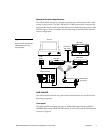
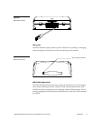
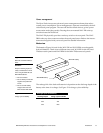
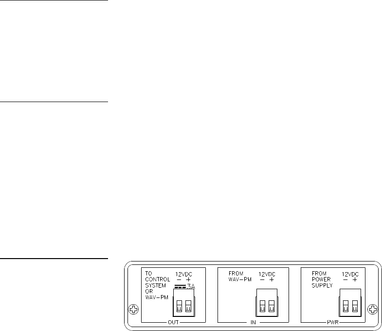
Rear panel
Figure 13 shows the WAV-PM WaveLink Power Module rear panel. Controls and
indicators are defined as follows.
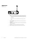
• OUT—This is a 2-wire connector which provides a 12 VDC, 3 AMP output
which can be connected to a WAV-LNK Control System or to another WAV-
PM module.
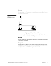
• IN—A 2-wire connector for accepting 12 VDC input power from another
WAV-PM module.
• PWR—When using power input from a separate 12 VDC power supply,
connect to this 2-wire connector.
Note
While a battery is charging, the
Empty/Full indicator does not
show a valid reading.
Caution
Ensure that the WAV-PM ap-
plication environment does not
require a greater supply cur-
rent than the module can pro-
vide. If the system is over-
loaded, irreparable damage
could occur to the module.
Figure 13
WAV-PM rear view