


WAVE 2
-Way Wireless Accessories and Adapters for Touch Panels Installation 25
Wiring guidelines
Wire size Maximum wiring length
18 AWG 1,174 feet
20 AWG 742 feet
22 AWG 463 feet
24 AWG 292 feet
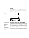
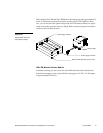
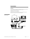
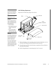
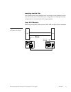
Do not install the AXR-WAVES farther away from the control system than recom-
mended in Figure 26.
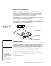
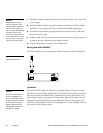
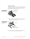
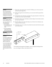
Preparing captive wires
You will need a wire stripper and flat-head screwdriver to perform these steps. Pre-
pare and connect the captive wires as follows.
1. Strip .25 inch of wire insulation off all wires.
2. Insert each wire into the appropriate opening on the connector according to the
wiring diagrams and connector types described in this section.
3. Turn the flat-head screws clockwise to secure the wire in the connector.
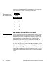
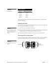
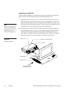
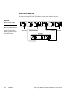
Connecting AXlink for data and power
Connect the control system’s AXlink connector to the AXlink connector on the rear
panel of the AXR-WAVES for data and 12 VDC power, as shown in Figure 27.
PWR(+)
PWR
AXM
AXM
AXP
AXP
GND (-)
GND
AXR-WAVES
AXCESS
Control System
Figure 26
Wiring guidelines
Caution
Do not over-torque the screw.
Doing so can bend the seat-
ing pin and damage the con-
nector.
Figure 27
AXlink data and power wiring
diagram