


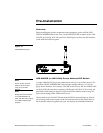

24 Installation WAVE 2-Way Wireless Accessories and Adapters for Touch Panels
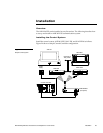
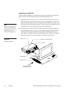
1. Mount the Central Controller in the position where it will be used. Connect the
power supply.
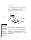
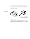
2. Place the AXR-WAVES in the position where it will be used. The RF antenna
should be set in a vertical position to communicate with the touch panels.
3. Position the touch panels, equipped with Wireless Power Packs, in the areas
where they will be used.
4. Multiple AXR-WAVES can be used in the same local servers/groups (up to 16)
as long as each has a different group address number.
5. Each server/group can contain up to 16 TiltScreens.
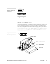
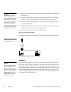
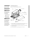
Wiring the AXR-WAVES
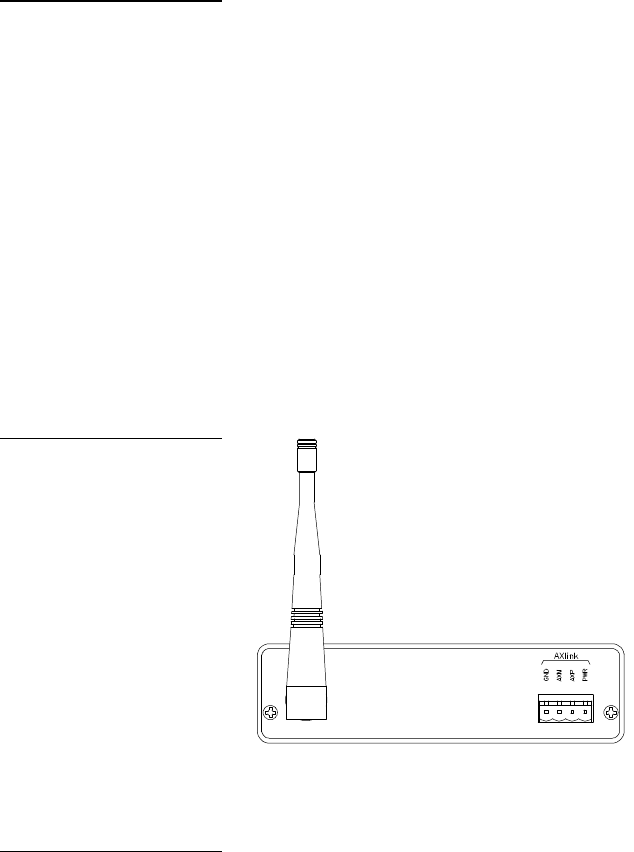
The AXR-WAVES rear panel contains an AXlink connector as shown in Figure 25.
Guidelines
The AXR-WAVES requires 12 VDC power to operate properly. The power is sup-
plied by the control system’s AXlink cable. The maximum wiring distance between
the control system and AXR-WAVES is determined by power consumption, sup-
plied voltage, and the wire gauge used for the cable. Figure 26 lists wire sizes and
maximum lengths allowable between the AXR-WAVES and control system. The
maximum wiring lengths are based on a minimum of 13.5 volts available at the con-
trol system’s power supply output.
Caution
AXR-WAVES uses spread-
spectrum signaling to avoid
common problems associated
with RF control. However, it's
wise not to place AXR-WAVES
components next to micro-
wave ovens, spread-spectrum
or consumer micro-wave video
link transceivers, or projectors
using Halide or Xenon lamps.
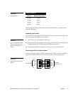
Figure 25
AXR-WAVES connector
Caution
Do not connect the AXlink ca-
ble to the AXR-WAVES yet.
Disconnect the wiring from the
CardFrame before con-necting
the AXlink cable to the AXR-
WAVES. Apply power to the
AXR-WAVES only when the
installation is complete.