


WAVE 2
-Way Wireless Accessories and Adapters for Touch Panels Firmware Upgrades 35
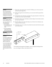
8. After removing the old firmware chip, position the new firmware chip on the
socket strips with the alignment notch over the top of the notch indicator on the
circuit board trace.
9. After positioning the firmware chip in the socket strips, apply sufficient down-
ward pressure to seat the chip in the socket strips.
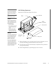
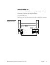
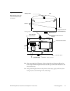
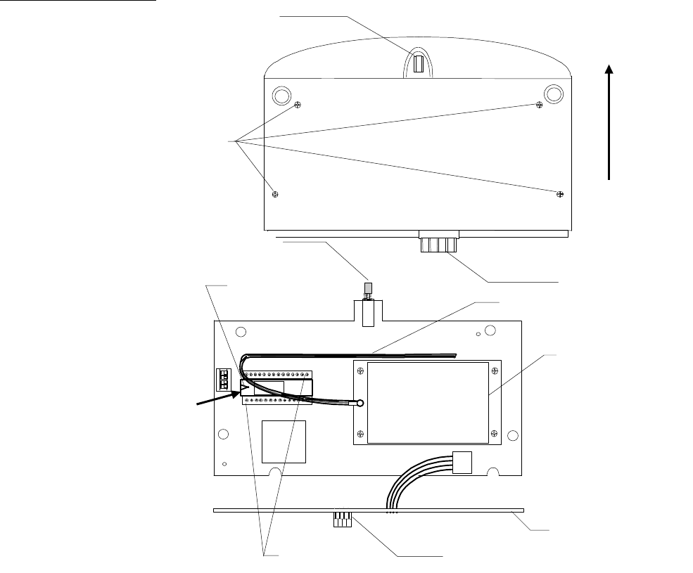
Figure 37
WAV-PK bottom cover remo-
val and circuit board compo-
nent location
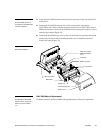
Wakeup button
AXlink connector
Screws
Wakeup button
Antenna
Bottom view-front
Rear
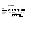
Connector board
AXlink connector
Lift up and to the rear
at the same time to
remove bottom cover
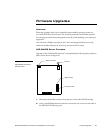
Integrated circuit
(IC) socket strips
Receive/transmit module
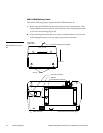
Under
and
up
To rear
Trace alignment
notch indicator