


34006452EN/AC - Page 17
Control panel
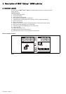
3.1 Visible control panel
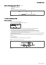
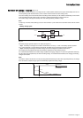
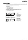
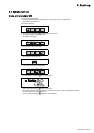
Visible control panel (Inverter or frequency converter cubicle)
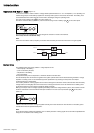
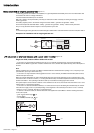
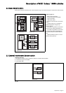
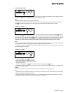
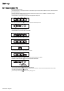
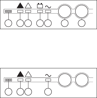
Visible control panel (Static Switch Cubicle)
Fig. 23
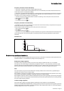
Located in the upper left part of the cubicle front, the visible panel is designed to provide an easy and rapid overview of system
status (see figures 22 and 23).
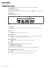
Interpretation of symbols is very simple and requires no particular training.
The information concerns only the cubicle on which the panel is located.
The panel indicates:
– normal operation (load protected);
– abnormal situations (operating problem);
– dangerous situations (load not protected);
– operation with load on battery power.
The control panel on the Static Switch Cubicle provides important information for the load:
– normal operation (load protected and supplied by the UPSs);
– abnormal situations (system malfunction);
– dangerous situations (load not protected).
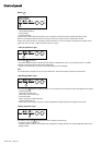
Legend for figure 22:
1-buzzer,
2-"load not protected" light
3-"operating problem" light
4-"load on battery" light
5-"load protected" light
6-"inverter on" button
7-"inverter off" button
Fig. 22
Legend for figure 23:
1-buzzer,
2-"load not protected" light
3-"operating problem" light
5-"load protected" light
5
I
+
!
!
O
4321 6 7
5
!
!
321