


34006452EN/AC - Page 9
Introduction
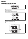
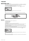
External maintenance bypass cubicle (figure 10)
1.5 Main operating modes
Normal operation
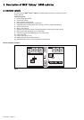
– Q3BP (switch) :
bypass switch for maintenance;
– Q5N (switch) :
isolation of the load from the parallel-connected UPSs.
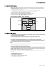
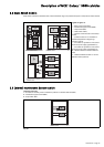
Fig. 10
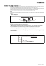
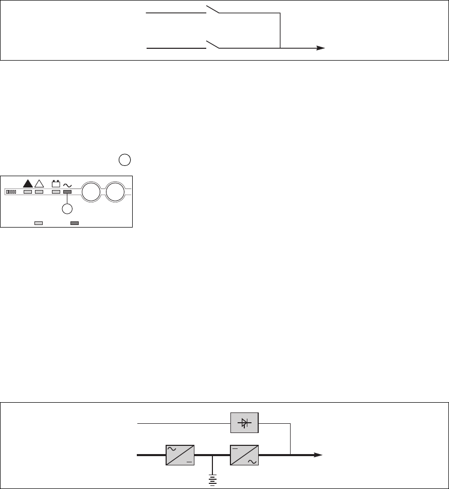
Mains 1 power is available: (see figure 11).
The green "load protected" light on the control panel is on.
The power necessary for the load is provided by Mains 1 through the rectifier-charger and the inverter.
The rectifier-charger also supplies the power to float charge and recharge the battery
(1)
.
The rectifier-charger output voltage (DC) is regulated for the different battery types and charging modes:
– vented lead-acid or Ni/Cd batteries: two different voltages, one for float charging and one for recharging;
– sealed lead-acid batteries: a single voltage for both charge functions.
The voltages depend on the number of battery cells and the battery manufacturer. They can be factory set and are adjustable
by the after-sales support technicians.
An optional electronic board may be used to continuously measure the battery temperature and automatically adjust the
voltages.
Parallel UPS systems:
the power drawn by the load is equally shared between the different UPSs.
(1) Except for frequency converters without a battery
Fig. 11
Q5N
Q3BP
parallel
modular UPSs
load
maintenance
bypass line
5
légend :
off on
5
I
+
!
!
O
mains 1
rectifier-
charger
battery
inverter
load
static switch
mains 2