


34006452EN/AC - Page 27
Start-up
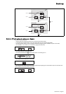
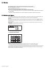
Parallel UPS systems with a Static Switch Cubicle
4.2 Start-up of a unit
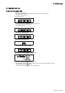
Start-up of a rectifier/charger
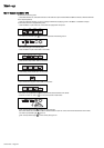
Start-up of an inverter
Single-unit or modular UPS system:
Frequency converter or multi-bypass UPS:
Modular UPS with external maintenance bypass or parallel UPS with SSC:
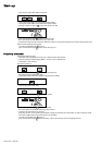
Frequency converter without a battery:
Proceed in the following order:
– check that all lines supplying the load are off or that the load is disconnected;
– close the upstream switches supplying Mains 1 and 2 power (on the LV switchboard);
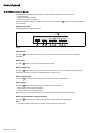
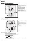
– close fuse switch Q2 in the Static Switch Cubicle (see figure 19);
– close Mains 2 input switch Q4S in the Static Switch Cubicle;
– close switch Q5N in the Static Switch Cubicle;
– open maintenance bypass switch Q3BP in the Static Switch Cubicle;
– close fuse switch Q1 in the Static Switch Cubicle;
– close input switch Q1 on an UPS line.
The line powers up;
– red "load not protected" light on the line control panel goes on,
– the RC automatically starts;
– close the line battery circuit breaker QF1;
– close inverter output switch Q5N for the line;
– press the "inverter on" button on the line control panel;
– green "load protected" light blinks for 3 seconds,
– the inverter starts and awaits the start of the other inverters;
– proceed in the same manner for each line;
– when they are all on or enough have been started to supply the rated load power, the output switch for each running line
closes and the load is supplied with power;
– red "load not protected" light goes off,
– green "load protected" light remains on, without blinking, on the control panel of each line supplying the load.
– it is recommended not to stop the rectifier/charger because the battery will no longer be charged. Rectifier/charger start-up
is automatic when Mains 1 input switch Q1 is closed;
– red "load not protected" light on the control panel goes on;
– close battery circuit breaker QF1.
When the rectifier/charger is on:
– press the "inverter on" button on the control panel;
– green "load protected" light blinks for 3 seconds;
– the inverter starts and if the transfer to Mains 2 conditions are correct, the load is supplied by the inverter;
– red "load not protected" light goes off,
– green "load protected" light becomes constant.
– the inverter starts and awaits the start of the other inverters;
– when they are all on or enough have been started to supply the rated load power, the output switch for each running line
closes and the load is supplied with power;
– red "load not protected" light goes off,
– green "load protected" light becomes constant, on the control panel of each line supplying the load.
– the inverter starts and awaits the start of the other inverters;
– when they are all on or enough have been started to supply the rated load power, the output switch for each running line
closes and the load is supplied with power;
– red "load not protected" light goes off,
– green "load protected" light remains on, without blinking, on the control panel of each line supplying the load and on
the control panel of the Static Switch Cubicle.
– Start-up of the rectifier/charger automatically leads to start-up of the inverter.
2
6
5
2
5
2
6
5
2
5
2
5
2
5