


34006452EN/AC - Page 24
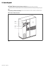
Start-up
Multi-bypass modular UPS
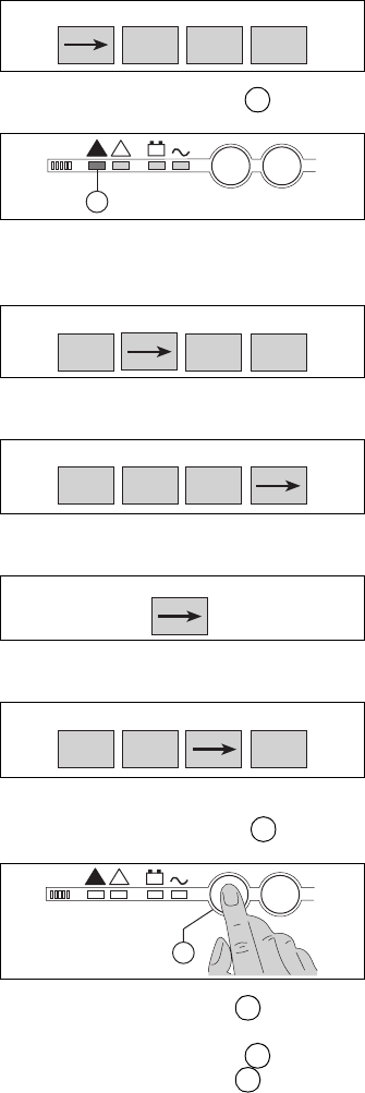
Proceed in the following order:
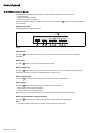
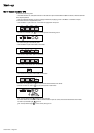
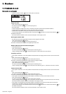
– check that switches Q1, Q4S, Q5N and QF1 on the UPSs are open and that switches Q3BP are closed, otherwise set them
to the required position;
– close the upstream switches (on the low-voltage switchboard) supplying power to the Mains 1 and Mains 2 inputs
on the UPSs, the load is supplied with power;
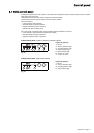
– close the Mains 1 input switch Q1 on the UPSs to supply them with power:
– red "load not protected" light on the control panels of the UPSs goes on:
– the rectifier/chargers automatically start;
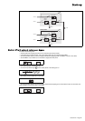
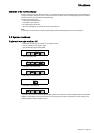
– close the Mains 2 input switch Q4S on the UPSs:
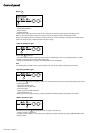
– close inverter output switch Q5N on the UPSs:
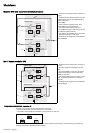
– close battery circuit breaker QF1 on the UPSs:
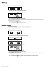
– open maintenance bypass switch Q3BP on the UPSs:
– the load is now supplied by the Mains 2 input via the static switches of the UPSs.
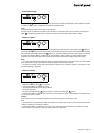
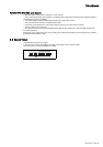
– press the "inverter on" button on the control panel of each UPSs:
green "load protected" light flashes for three seconds,
the inverter starts and, if transfer conditions with the Mains 2 input are correct, the load is transferred to the inverter,
red "load not protected" light goes off,
green "load protected" light on the control panel goes on.
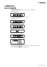
Q1 Q4S Q3BP Q5N
OFF
ON
(0)
(I)
OFF
(0)
ON
(I)
OFF
(0)
2
I
+
!
!
O
2
Q1 Q4S Q3BP Q5N
OFF
ON
(0)
(I)
ON
(I)
ON
(I)
OFF
(0)
Q1 Q4S Q3BP Q5N
OFF
ON
(0)
(I)
ON
(I)
ON
(I)
ON
(I)
QF1
OFF
ON
(0)
(I)
Q1 Q4S Q3BP Q5N
ON
OFF
(I)
(0)
ON
(I)
ON
(I)
ON
(I)
6
I
+
!
!
O
6
5
2
5