


34006452EN/AC - Page 35
Environment information
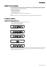
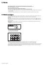
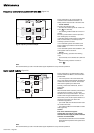
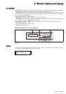
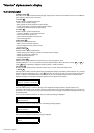
Signal reception
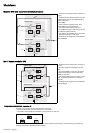
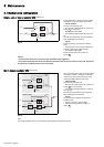
Signal transmission
The signals should be provided by volt-free contacts.
– "desynchronization with Mains 2" signal inhibits the inverter from synchronizing its output frequency with that of
Mains 2. The inverter supplies a stable frequency and the load may no longer be correctly transferred from the inverter to
Mains 2. In the event of a malfunction or an overload, the transfer will take place with a 0.8 second interruption in the supply
of power to the load;
– "gradual rectifier/charger shutdown" signal makes the rectifier/charger shut down progressively to avoid excessive step
load variations in the event of a low output engine generator set replacing Mains 1;
– "generator current limiting" signal makes the rectifier/charger current limit the power drawn when a low output engine
generator set has replaced Mains 1. The additional power required for the inverter is supplied by the battery;
– "battery charge current limiting" signal reduces the battery charge current (programmable parameter) in the event a low
output engine generator set has replaced Mains 1;
– "transfer to Mains 2 disabled" signal blocks transfer of the load from the inverter to Mains 2. In the event the inverter
shuts down (overload, etc.), the load is no longer supplied (for modular UPSs, this information is disabled and transferred to
an auxiliary output);
– "transfer to Mains 2 with interruption disabled" signal blocks transfer of the load from the inverter to Mains 2 if it would
result in an interruption in the supply of power to the load. Only no-break transfers are allowed, i.e. transfer to Mains 2
conditions must be correct or the transfer is disabled (for modular UPSs, this information is disabled and transferred to an
auxiliary output);
– "auxiliary" signal can be used to provoke (depending on personalization):
a forced shutdown of the inverter (regardless of the status of Mains 2),
a protected inverter shutdown (transfer of the load to Mains 2 without interruption only if it is within tolerances),
modification of the inverter output frequency (50 Hz or 60 Hz);
– "remote inverter on" signal can be used to remotely start the inverter;
– "remote inverter off" signal can be used to remotely shut down the inverter.
Note:
In a system with a Static Switch Cubicle, the following signals must be directed to the Static Switch Cubicle:
– desynchronization with Mains 2,
– transfer to Mains 2 disabled,
– transfer to Mains 2 with interruption disabled.
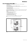
These signals are each transmitted by two volt-free changeover contacts with a maximum breaking capacity of 5 A 250 V.
– "overload" signal indicates that an overload has taken place (Pload > Pnominal in kVA);
– "rectifier/charger function fault" signal indicates that:
– a fault has taken place in the rectifier/charger module,
– Mains 1 input switch Q1 is open;
– "inverter function fault" signal indicates that a fault has taken place in the inverter module;
– "transfer to inverter fault" signal indicates that the load transfer conditions from Mains 2 to the inverter are incorrect;
– "transfer to Mains 2 fault" signal indicates that the transfer to Mains 2 conditions (voltage, frequency or phase) are
incorrect and a forced transfer will result in a 0.8 second interruption in the supply of power to the load;
– "rectifier/charger on" signal indicates the status of the module.
Note:
A Static Switch Cubicle receives only the following signals:
– overload,
– transfer to inverter fault,
– transfer to Mains 2 fault.