


34006452EN/AC - Page 37
Maintenance
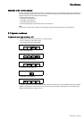
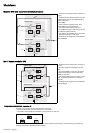
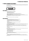
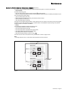
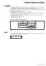
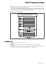
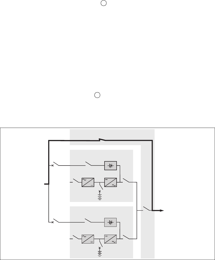
Modular UPS with external maintenance bypass (figure 27)
To service a number of modular UPSs with an external maintenance bypass, it is necessary to isolate them.
– isolate the UPSs
Proceed in the following order:
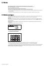
– shut down each inverter (press the "inverter off" button for three seconds),
– switch to the maintenance bypass whereby the load will be directly supplied by Mains 2 via Q3BP (close Q3BP, then open
Q5 in the maintenance bypass cubicle),
– open input switch Q4S on each UPS;
– isolate each UPS from Mains 2 by opening the upstream protection devices,
– open input switch Q1 on each UPS,
– open output switch Q5N on each UPS.
The UPSs are de-energised (except the Mains 1 cables upstream of the Q1 switches on each UPS), but the load is supplied
with Mains 2 power via the maintenance bypass. Complete isolation of the installation requires opening of the upstream
protection devices on both Mains 1 and Mains 2.
– start-up
Once servicing is completed, proceed in the following order:
– close the input switches Q1 and Q4S on each UPS,
– close output switch Q5N on each UPS,
– close output switch Q5N in the maintenance bypass cubicle,
– open switch Q3BP in the maintenance bypass cubicle,
– close battery circuit breaker Q1 on each UPS,
– start all the inverters (press the "inverter on" button ).
The UPSs all come on line at the same time if they are sufficient in number to supply the load.
Note:
It is strongly advised to call on our after-sales support department for these operations.
Fig. 27
7
6
Q1
Q5N
QF1
Q3BP
Q4S
Q1
Q5N
QF1
Q4S
Modular UPS 2
Modular UPS 1
Q5N
External maintenance bypass
load
battery
inverter
mains 1
rectifier-
charger
static switch
mains 2
battery
inverter
mains 1
rectifier-
charger
static switch
mains 2