


34006452EN/AC - Page 30
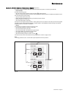
Shutdown
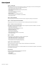
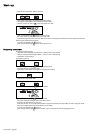
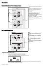
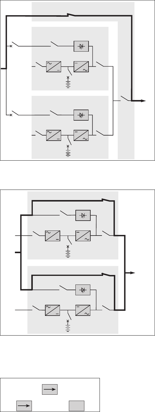
Modular UPS with external maintenance bypass
Frequency converters
(no Mains 2)
– shutdown each UPS (see section "shutdown of
a unit");
– transfer to the maintenance bypass in the order
indicated below (the load is supplied directly by
Mains 2 via bypass
switch Q3BP):
– in the maintenance bypass cubicle, close
switch Q3BP, then open switch Q5N;
– open output switch Q5N for each UPS;
– cut the Mains 2 supply to each UPS by opening
the upstream protection devices;
– open battery circuit breaker QF1 on each UPS;
– open input switch Q1 on each UPS;
– the UPSs are de-energised once the capacitors
have discharged.
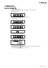
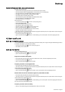
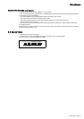
Multi-bypass modular UPS
– shutdown each UPS (see section "shutdown of
a unit");
– the load is supplied via the Mains 2 of each
UPS;
– close switch Q3BP on each UPS, the load is
supplied by the Mains 2, via the bypass lines
(Q3BP) of each UPS;
– open switches Q5N, Q4S, Q1 and QF1 on each
UPS, the situation is that shown in the figure
opposite;
– the UPSs are de-energised once the capacitors
have discharged.
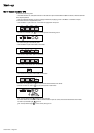
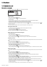
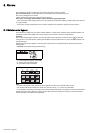
Shutdown of the inverters results in the interruption of the load;
– shut down each inverter (see the "shutdown of a unit" section);
– open battery circuit breaker QF1 and Mains 1 input switch Q1 on each unit;
– the system is powered down (except the Mains 1 cables upstream from switch Q1). A full powering down requires the
opening of the upstream protection device on Mains 1.
Q1
Q5N
QF1
Q3BP
Q4S
Q1
Q5N
QF1
Q4S
Modular UPS 2
Modular UPS 1
Q5N
External maintenance bypass
load
battery
inverter
mains 1
rectifier-
charger
static switch
mains 2
battery
inverter
mains 1
rectifier-
charger
static switch
mains 2
Q1
Q5N
QF1
Q3BP
Q4S
Q1
Q5N
QF1
Q3BP
Q4S
Modular UPS 2
Modular UPS 1
load
battery
inverter
mains 1
rectifier-
charger
static switch
battery
inverter
mains 1
rectifier-
charger
static switch
mains 2
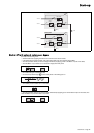
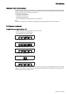
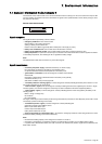
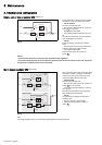
Q1 Q5N
ON
OFF
(I)
(0)
ON
(I)
QF1
OFF
ON
(0)
(I)