1.4.1 LEDs
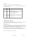
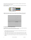
The IC39240/480 front panel LED display allows you to monitor the status of the switch.
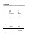
The IC39240/480 has one power LED indicator. There are also LED indicators for each of the ports. Refer to the
following table for LED information.
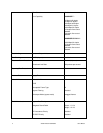
LED Color Description
Power Green
Off
Power is on.
Power is off, or main power has failed.
1000MBps Amber
Green
Off
A valid 1000 Mbps link has been established on the port.
A valid 10/100 Mbps link has been established on the port.
No link has been established on the port.
Link/Activity Green
Blinking Green
Off
A link has been established on the port.
Activity has been detected.
No link has been established on the port.
1.5 Management and Configuration
The switch is managed using Command Line Interface (CLI) in order to access several different command modes.
Entering a question mark (?) at each command mode’s prompt provides a list of commands.
1.5.1 Console Interface
Support for local, out-of-band management is delivered through a terminal or modem attached to the EIA/TIA-232
interface. You can access the switch by connecting a PC or terminal to the console port of the switch, via a serial
cable. The default uername/ password set on the console line is admin/Asante (it is case-sensitive). The default IP
address is 192.168.0.1. It can be modified to suit your network setup. See 3.4 for details.
Remote in-band management is available through Simple Network Management Protocol (SNMP) and Telnet client.
When connecting via a Telnet session, the default login/password is also admin/Asante (case-sensitive).
See Chapter 2 for more information on connecting to the switch.
13 Asante IntraCore IC39240/480 User’s Manual


