


2-242-24
2-242-24
2-24
Chapter 2: Hardware informationChapter 2: Hardware information
Chapter 2: Hardware informationChapter 2: Hardware information
Chapter 2: Hardware information
5.5.
5.5.
5.
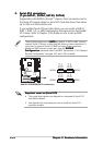
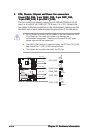
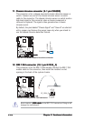
CPU, Chassis, Chipset and Power fan connectorsCPU, Chassis, Chipset and Power fan connectors
CPU, Chassis, Chipset and Power fan connectorsCPU, Chassis, Chipset and Power fan connectors
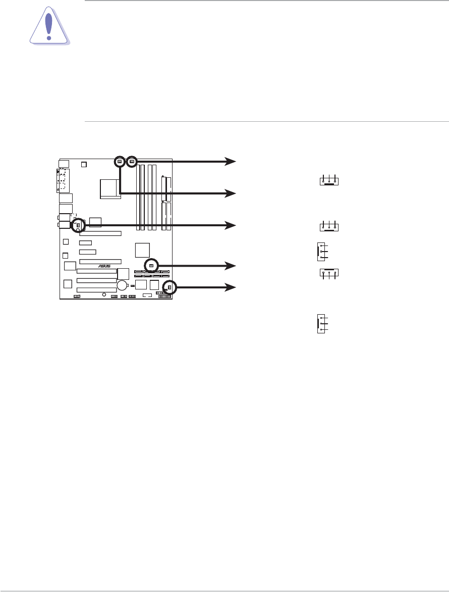
CPU, Chassis, Chipset and Power fan connectors
(3-pin CPU_FAN, 3-pin CHA2_FAN, 3-pin CHIP_FAN,(3-pin CPU_FAN, 3-pin CHA2_FAN, 3-pin CHIP_FAN,
(3-pin CPU_FAN, 3-pin CHA2_FAN, 3-pin CHIP_FAN,(3-pin CPU_FAN, 3-pin CHA2_FAN, 3-pin CHIP_FAN,
(3-pin CPU_FAN, 3-pin CHA2_FAN, 3-pin CHIP_FAN,
3-pin PWR_FAN, 3-pin CHA1_FAN) 3-pin PWR_FAN, 3-pin CHA1_FAN)
3-pin PWR_FAN, 3-pin CHA1_FAN) 3-pin PWR_FAN, 3-pin CHA1_FAN)
3-pin PWR_FAN, 3-pin CHA1_FAN)
The fan connectors support cooling fans of 350mA~2000mA (24 W
max.) or a total of 1A~3.48A (41.76 W max.) at +12V. Connect the
fan cables to the fan connectors on the motherboard, making sure that
the black wire of each cable matches the ground pin of the connector.
• Do not forget to connect the fan cables to the fan connectors. Lack
of sufficient air flow inside the system may damage the
motherboard components. These are not jumpers! DO NOT place
jumper caps on the fan connectors!
• The ASUS Q-Fan function is supported using the CPU Fan (CPU_FAN)
and Chassis Fan 1 (CHA1_FAN) connectors only.
• The chipset fan is synchronized with the CPU fan.
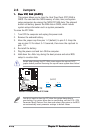
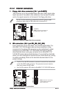
A8N-SLI PREMIUM
®
A8N-SLI PREMIUM Fan connectors
CPU_FAN
CHA1_FAN
PWR_FAN
CHA2_FAN
GND
Rotation
+12V
GND
Rotation
+12V
GND
Rotation
+12V
GND
Rotation
+12V
CPU_FAN
CHA1_FAN
PWR_FAN
CHA2_FAN
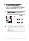
CHIP_FAN
GND
Rotation
+12V
CHIP_FAN