


2-202-20
2-202-20
2-20
Chapter 2: Hardware informationChapter 2: Hardware information
Chapter 2: Hardware informationChapter 2: Hardware information
Chapter 2: Hardware information
3.3.
3.3.
3.
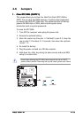
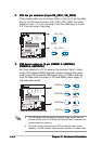
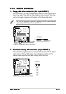
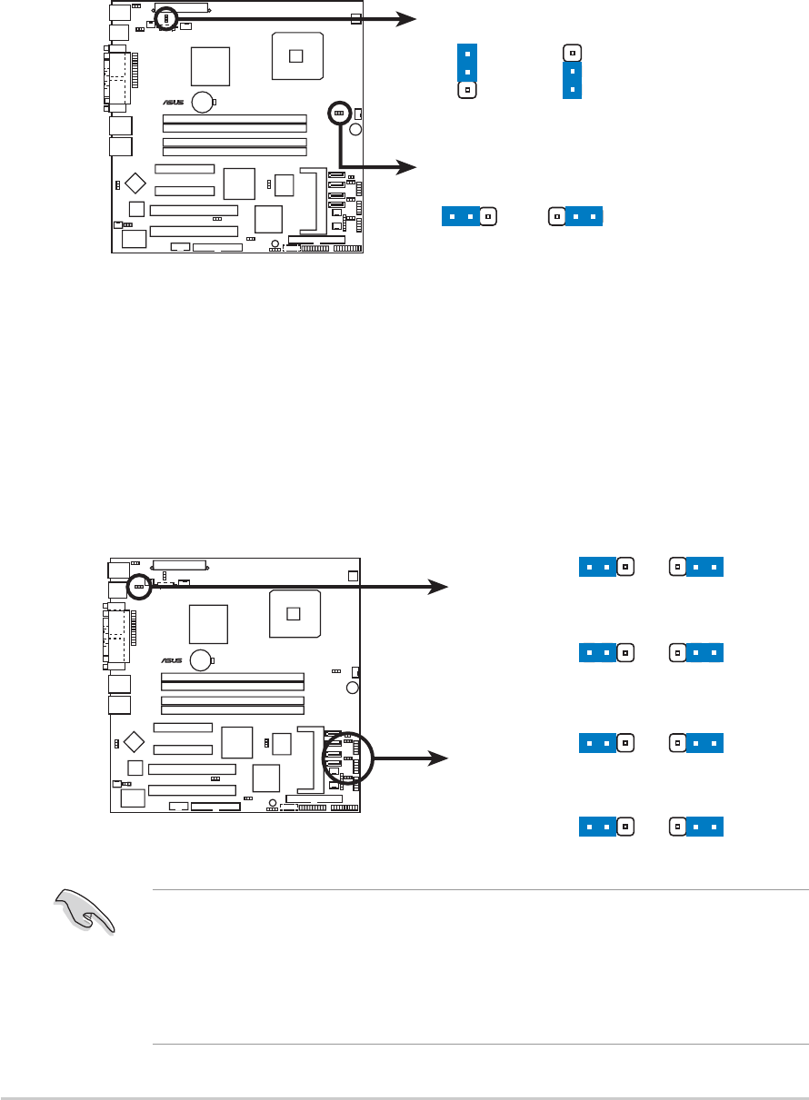
USB device wake-up (3-pin USBPW12, USBPW34,USB device wake-up (3-pin USBPW12, USBPW34,
USB device wake-up (3-pin USBPW12, USBPW34,USB device wake-up (3-pin USBPW12, USBPW34,
USB device wake-up (3-pin USBPW12, USBPW34,
USBPW56, USBPW78)USBPW56, USBPW78)
USBPW56, USBPW78)USBPW56, USBPW78)
USBPW56, USBPW78)
Set these jumpers to +5V to wake up the computer from S1 sleep
mode (CPU stopped, DRAM refreshed, system running in low power
mode) using the connected USB devices. Set to +5VSB to wake up
from S4 sleep mode (no power to CPU and DRAM, power supply in
reduced power mode).
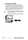
•
The USB device wake-up feature requires a power supply that can
provide 500mA on the +5VSB lead for each USB port; otherwise, the
system would not power up.
•
The total current consumed must NOT exceed the power supply
capability (+5VSB) whether under normal condition or in sleep mode.
2.2.
2.2.
2.
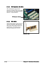
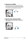
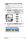
CPU fan pin selection (3-pin FM_CPU1, FM_CPU2)CPU fan pin selection (3-pin FM_CPU1, FM_CPU2)
CPU fan pin selection (3-pin FM_CPU1, FM_CPU2)CPU fan pin selection (3-pin FM_CPU1, FM_CPU2)
CPU fan pin selection (3-pin FM_CPU1, FM_CPU2)
These jumpers allow you to connect either a 3-pin or a 4-pin fan cable
plug to the CPU fan connectors (CPU_FAN1, CPU_FAN2). Set these
jumpers to pins 1-2 if you are using a 3-pin fan cable plug, or to pins
2-3 if you are using a 4-pin plug.
P5MT-M
LAN2
®
P5MT-M FM CPU Setting
FM_CPU1
FM_CPU2
12 23
3-pin fan 4-pin fan
(Default)
2
3
2
1
3-pin fan 4-pin fan
(Default)
P5MT-M
LAN2
®
P5MT-M USB device wake-up
USBPW12
(Defaul
t)
+5V+5VSB
2132
USBPW78
USBPW56
USBPW34
(Defaul
t)
+5V+5VSB
21
32
(Defaul
t)
+5V+5VSB
21
32
(Defaul
t)
+5V+5VSB
21
32