


2-262-26
2-262-26
2-26
Chapter 2: Hardware informationChapter 2: Hardware information
Chapter 2: Hardware informationChapter 2: Hardware information
Chapter 2: Hardware information
3.3.
3.3.
3.
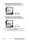
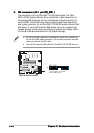
IDE connector (40-1 pin PRI_IDE1)IDE connector (40-1 pin PRI_IDE1)
IDE connector (40-1 pin PRI_IDE1)IDE connector (40-1 pin PRI_IDE1)
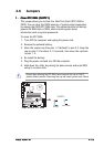
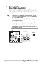
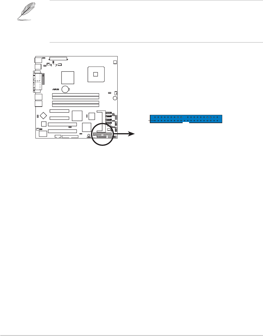
IDE connector (40-1 pin PRI_IDE1)
This connector is for an Ultra DMA 100/66 signal cable. The Ultra
DMA 100/66 signal cable has three connectors: a blue connector for
the primary IDE connector on the motherboard, a black connector for
an Ultra DMA 100/66 IDE slave device (optical drive/hard disk drive),
and a gray connector for an Ultra DMA 100/66 IDE master device (hard
disk drive). If you install two hard disk drives, you must configure the
second drive as a slave device by setting its jumper accordingly. Refer
to the hard disk documentation for the jumper settings.
• Pin 20 on the IDE connector is removed to match the covered hole
on the Ultra DMA cable connector. This prevents incorrect insertion
when you connect the IDE cable.
• Use the 80-conductor IDE cable for Ultra DMA 100/66 IDE devices.
P5MT-M
LAN2
®
P5MT-M IDE connector
NOTE: Orient the red markings
(usually zigzag) on the IDE
ribbon cable to PIN 1.
PRI_IDE1
PIN 1