


2-282-28
2-282-28
2-28
Chapter 2: Hardware informationChapter 2: Hardware information
Chapter 2: Hardware informationChapter 2: Hardware information
Chapter 2: Hardware information
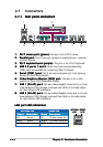
6.6.
6.6.
6.
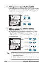
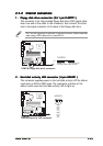
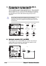
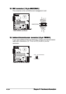
Serial port connector (10-1 pin COM2)Serial port connector (10-1 pin COM2)
Serial port connector (10-1 pin COM2)Serial port connector (10-1 pin COM2)
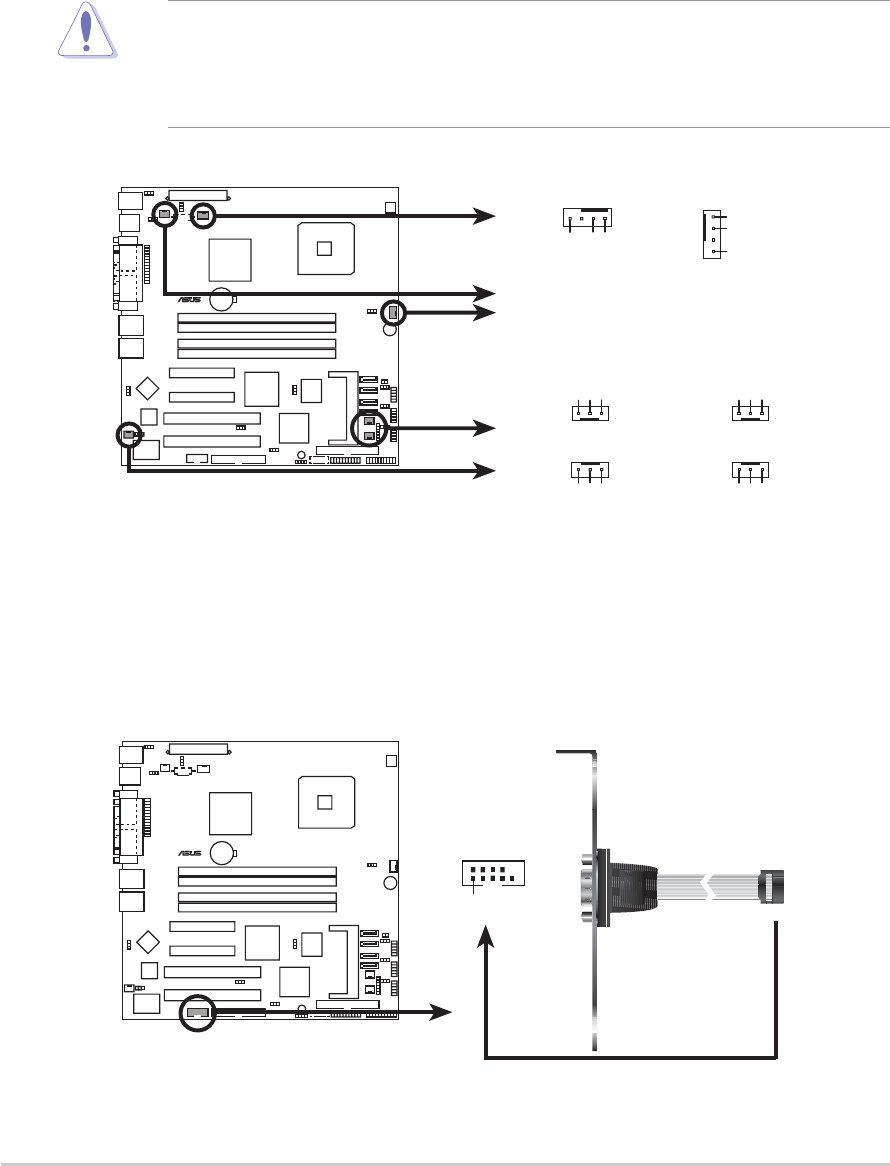
Serial port connector (10-1 pin COM2)
This connector is for a serial (COM2) port. Connect the serial port
module cable to this connector, then install the module to a slot
opening at the back of the system chassis.
5.5.
5.5.
5.
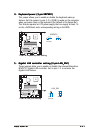
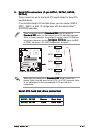
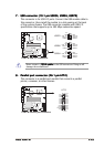
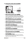
CPU and system fan connectors (4-pin CPU_FAN1/2,CPU and system fan connectors (4-pin CPU_FAN1/2,
CPU and system fan connectors (4-pin CPU_FAN1/2,CPU and system fan connectors (4-pin CPU_FAN1/2,
CPU and system fan connectors (4-pin CPU_FAN1/2,
3-pin REAR_FAN1/2, 3-pin FRNT_FAN1/2)3-pin REAR_FAN1/2, 3-pin FRNT_FAN1/2)
3-pin REAR_FAN1/2, 3-pin FRNT_FAN1/2)3-pin REAR_FAN1/2, 3-pin FRNT_FAN1/2)
3-pin REAR_FAN1/2, 3-pin FRNT_FAN1/2)
The fan connectors support cooling fans of 350 mA ~ 740 mA (8.88 W
max.) or a total of 2.1 A ~ 4.44 A (53.28 W max.) at +12V. Connect
the fan cables to the fan connectors on the motherboard, making sure
that the black wire of each cable matches the ground pin of the
connector.
Do not forget to connect the fan cables to the fan connectors.
Insufficient air flow inside the system may damage the motherboard
components. These are not jumpers! Do not place jumper caps on the
fan connectors!
P5MT-M
LAN2
®
P5MT-M Fan connectors
REAR_FAN
2
REAR_FAN1
FRNT_FAN1 FRNT_FAN
2
GND
FANPWR2
FANOUT4
CPU_FAN2CPU_FAN1
GND
FANPWR3
FANOUT7
GND
Rotation
+12V
CPU_FAN2
REAR_FAN2
REAR_FAN1
FRNT_FAN1
FRNT_FAN2
CPU_FAN1
GND
Rotation
+12V
GND
Rotation
+12V
GND
Rotation
+12V
P5MT-M
LAN2
®
P5MT-M
Serial port2 (COM2) connector
PIN 1
COM2