


ASUS P5MT-MASUS P5MT-M
ASUS P5MT-MASUS P5MT-M
ASUS P5MT-M
2-252-25
2-252-25
2-25
2.7.22.7.2
2.7.22.7.2
2.7.2
Internal connectorsInternal connectors
Internal connectorsInternal connectors
Internal connectors
1.1.
1.1.
1.
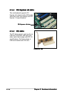
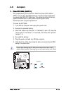
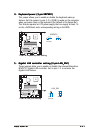
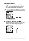
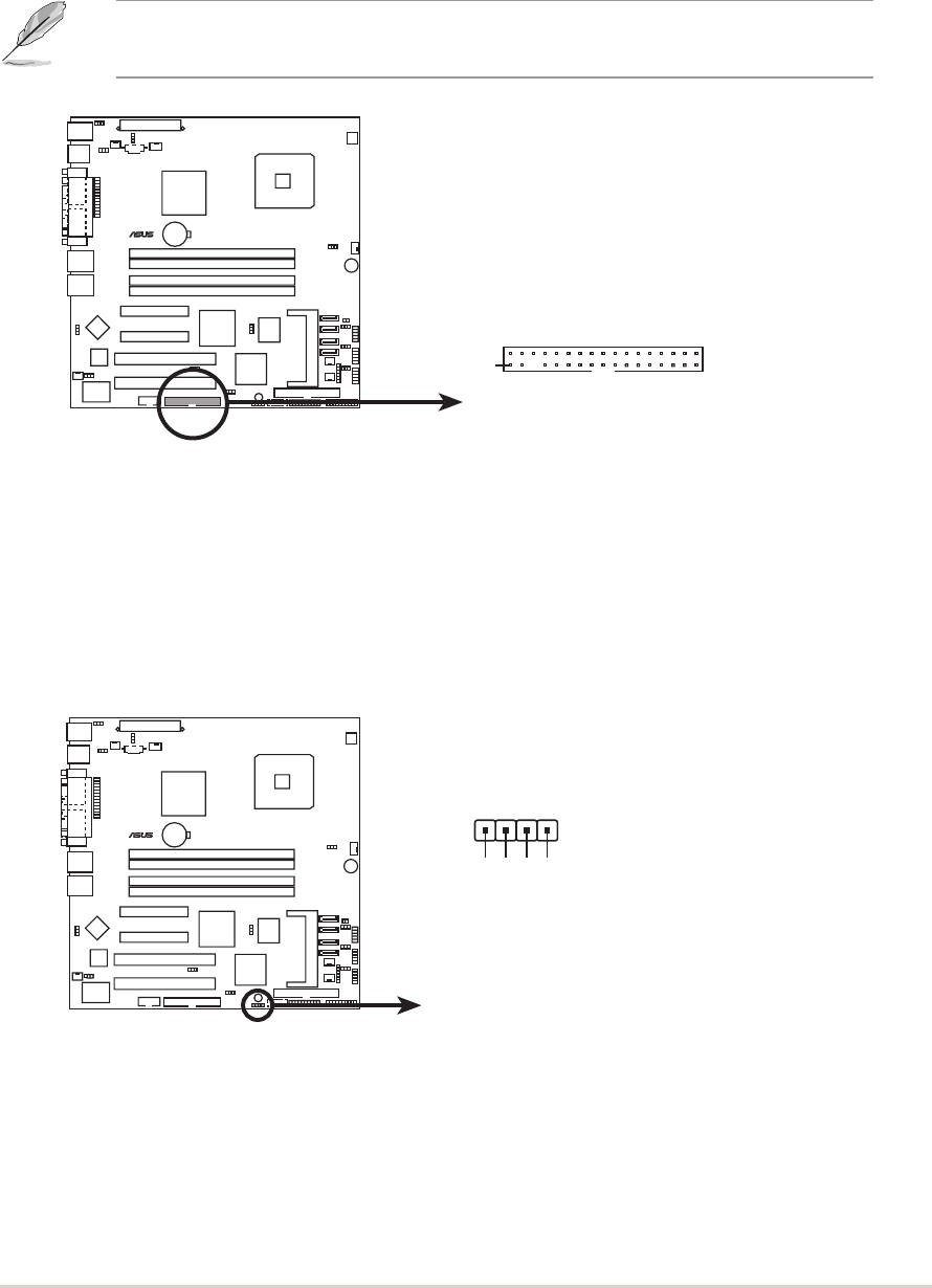
Floppy disk drive connector (34-1 pin FLOPPY1)Floppy disk drive connector (34-1 pin FLOPPY1)
Floppy disk drive connector (34-1 pin FLOPPY1)Floppy disk drive connector (34-1 pin FLOPPY1)
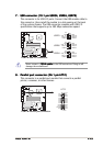
Floppy disk drive connector (34-1 pin FLOPPY1)
This connector is for the provided floppy disk drive (FDD) signal cable.
Insert one end of the cable to this connector, then connect the other
end to the signal connector at the back of the floppy disk drive.
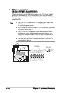
Pin 5 on the connector is removed to prevent incorrect cable connection
when using a FDD cable with a covered Pin 5.
2.2.
2.2.
2.
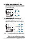
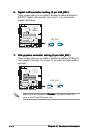
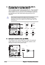
Hard disk activity LED connector (4-pin HDLED1)Hard disk activity LED connector (4-pin HDLED1)
Hard disk activity LED connector (4-pin HDLED1)Hard disk activity LED connector (4-pin HDLED1)
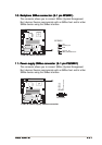
Hard disk activity LED connector (4-pin HDLED1)
This connector supplies power to the hard disk activity LED for add-on
cards such as SCSI or RAID cards. The read/write activities of the
add-on cards cause the hard disk activity LED to light up.
P5MT-M
LAN2
®
NOTE: Orient the red markings o
n
the floppy ribbon cable to PIN 1.
P5MT-M Floppy disk drive connector
FLOPPY1
PIN 1
P5MT-M
LAN2
®
P5MT-M
Hard disk activity LED connector
HDLED
1
1
ADD_IN_CARD_ACT#
NC
ADD_IN_CARD_ACT#
NC