


2-302-30
2-302-30
2-30
Chapter 2: Hardware informationChapter 2: Hardware information
Chapter 2: Hardware informationChapter 2: Hardware information
Chapter 2: Hardware information
9.9.
9.9.
9.
SSI SSI
SSI SSI
SSI
power connectorspower connectors
power connectorspower connectors
power connectors
(24-pin ATXPWR1,(24-pin ATXPWR1,
(24-pin ATXPWR1,(24-pin ATXPWR1,
(24-pin ATXPWR1,
4 4
4 4
4
-pin -pin
-pin -pin
-pin
ATXATX
ATXATX
ATX
12V1)12V1)
12V1)12V1)
12V1)
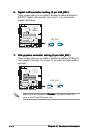
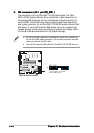
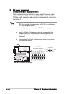
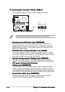
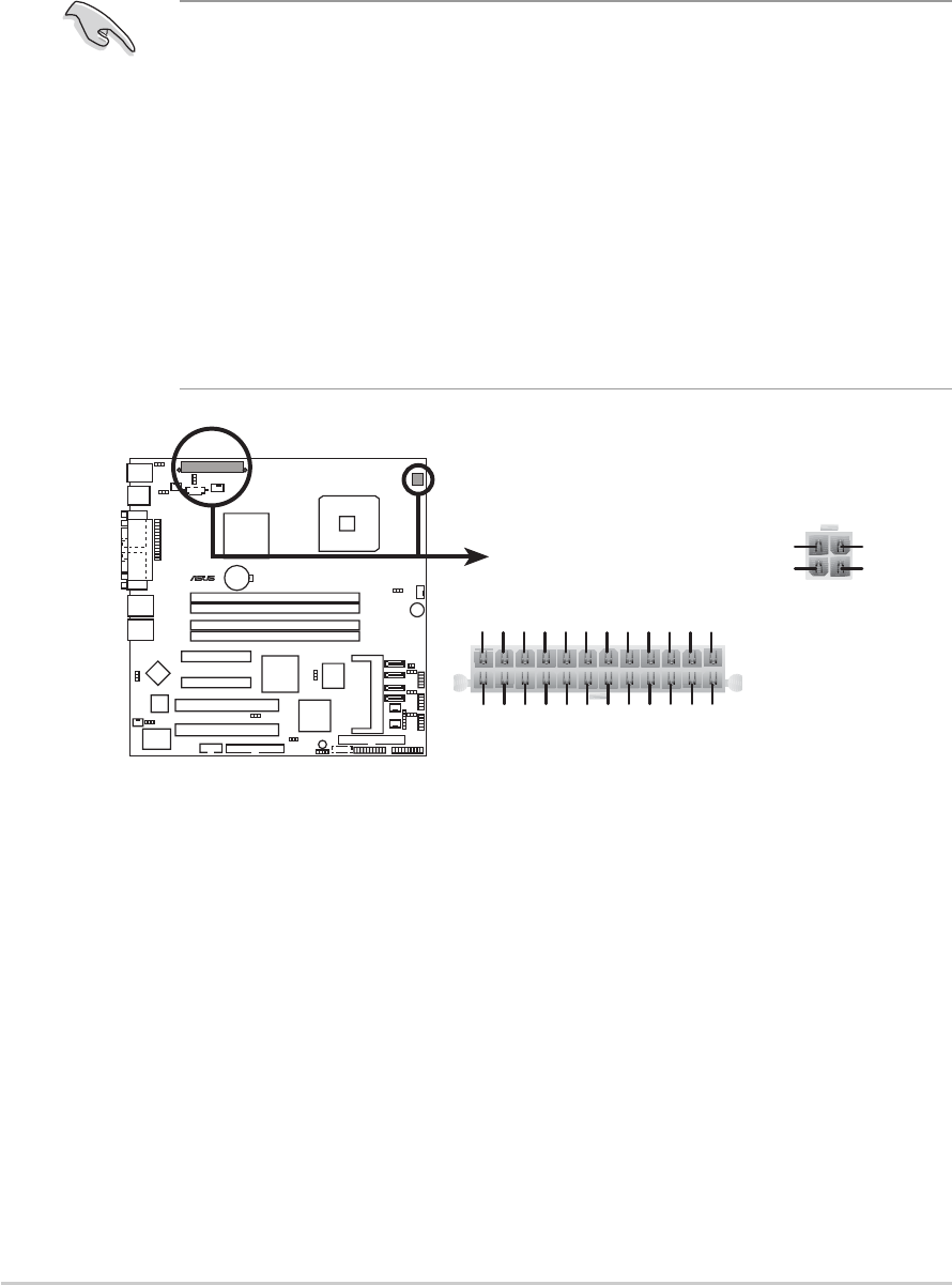
These connectors are for SSI power supply plugs. The power supply
plugs are designed to fit these connectors in only one orientation.
Find the proper orientation and push down firmly until the connectors
completely fit.
• Use of an SSI 12 V Specification 2.0-compliant power supply unit
(PSU) that provides a minimum power of 450 W is recommended
for a fully-configured system.
• Do not forget to connect the 4-pin ATX12V1 power plug; otherwise,
the system will not boot up.
• Use of a PSU with a higher power output is recommended when
configuring a system with more power consuming devices. The
system may become unstable or may not boot up if the power is
inadequate.
• You must install a PSU with a higher power rating if you intend to
install additional devices.
P5MT-M
LAN2
®
P5MT-M ATX power connectors
24-pin Power Connector
ATX12V1
+12V DC
GND
+12V DC
GND
ATXPWR1
+3 Volts
+3 Volts
Ground
+5 Volts
+5 Volts
Ground
Ground
Power OK
+5V Standby
+12 Volts
-5 Volts
+5 Volts
+3 Volts
-12 Volts
Ground
Ground
Ground
PSON#
Ground
+5 Volts
+12 Volts
+3 Volts
+5 Volts
1
Ground