


4-64-6
4-64-6
4-6
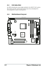
Chapter 4: Motherboard infoChapter 4: Motherboard info
Chapter 4: Motherboard infoChapter 4: Motherboard info
Chapter 4: Motherboard info
5.5.
5.5.
5.
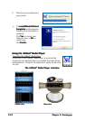
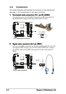
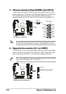
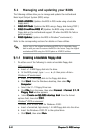
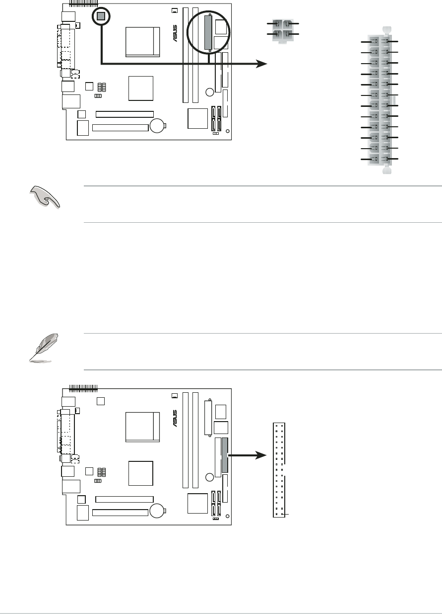
ATX power connectors (24-pin EATXPWR, 4-pin ATX12V)ATX power connectors (24-pin EATXPWR, 4-pin ATX12V)
ATX power connectors (24-pin EATXPWR, 4-pin ATX12V)ATX power connectors (24-pin EATXPWR, 4-pin ATX12V)
ATX power connectors (24-pin EATXPWR, 4-pin ATX12V)
These connectors are for the 24-pin and 4-pin power plugs from the
power supply unit. The plugs from the power supply unit are designed
to fit these connectors in only one orientation. Find the proper
orientation and push down firmly until the connectors completely fit.
Do not forget to connect the 4-pin ATX12V power plug to the ATX12V
connector on the motherboard; otherwise, the system will not boot up.
6.6.
6.6.
6.
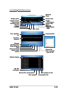
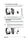
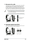
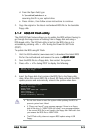
Floppy disk drive connector (34-1 pin FLOPPY)Floppy disk drive connector (34-1 pin FLOPPY)
Floppy disk drive connector (34-1 pin FLOPPY)Floppy disk drive connector (34-1 pin FLOPPY)
Floppy disk drive connector (34-1 pin FLOPPY)
This connector is for the provided floppy disk drive (FDD) signal cable.
Insert one end of the cable to this connector, then connect the other
end to the signal connector at the back of the floppy disk drive.
Pin 5 on the connector is removed to prevent incorrect cable connection
when using an FDD cable with a covered Pin 5.
®
ATX power connectors
EATXPWR
+12V DC
GND
+12V DC
GND
ATX12V
+3 Volts
+3 Volts
Ground
+5 Volts
+5 Volts
Ground
Ground
Power OK
+5V Standby
+12 Volts
-5 Volts
+5 Volts
+3 Volts
-12 Volts
Ground
Ground
Ground
PSON#
Ground
+5 Volts
+12 Volts
+3 Volts
+5 Volts
Ground
®
Floppy disk drive connector
NOTE: Orient the red markings on
the floppy ribbon cable to PIN 1.
PIN 1
FLOPPY