


4-94-9
4-94-9
4-9
ASUS T2-AH1ASUS T2-AH1
ASUS T2-AH1ASUS T2-AH1
ASUS T2-AH1
10.10.
10.10.
10.
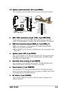
System panel connector (34-1 pin PANEL)System panel connector (34-1 pin PANEL)
System panel connector (34-1 pin PANEL)System panel connector (34-1 pin PANEL)
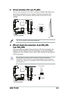
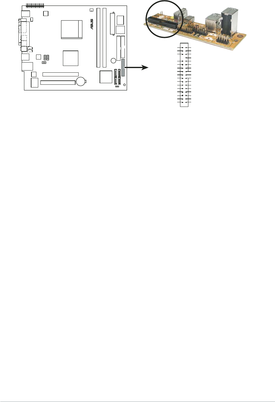
System panel connector (34-1 pin PANEL)
This connector accommodates several system front panel functions.
••
••
•
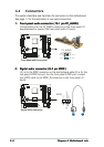
IEEE 1394 connectors (5-pin 1394, 6-pin IEEE1394)IEEE 1394 connectors (5-pin 1394, 6-pin IEEE1394)
IEEE 1394 connectors (5-pin 1394, 6-pin IEEE1394)IEEE 1394 connectors (5-pin 1394, 6-pin IEEE1394)
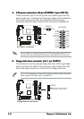
IEEE 1394 connectors (5-pin 1394, 6-pin IEEE1394)
These connectors are for the IEEE 1394a connectors on the front
panel I/O daughterboard to support the front panel IEEE 1394a ports.
••
••
•
USB 2.0 connectors (6-pin USB4_5, 7-pin USB6_7)USB 2.0 connectors (6-pin USB4_5, 7-pin USB6_7)
USB 2.0 connectors (6-pin USB4_5, 7-pin USB6_7)USB 2.0 connectors (6-pin USB4_5, 7-pin USB6_7)
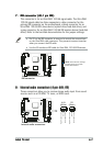
USB 2.0 connectors (6-pin USB4_5, 7-pin USB6_7)
USB4 is for connector on the storage card reader daughterboard.
USB5 is for the remote controller.
USB6 and USB7 are for the user’s USB devices to be connected on the
front I/O.
••
••
•
System power LED (1-pin PLED-)System power LED (1-pin PLED-)
System power LED (1-pin PLED-)System power LED (1-pin PLED-)
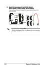
System power LED (1-pin PLED-)
This 1-pin connector is for the system power LED. The system power
LED lights up when you turn on the system power, and blinks when
the system is in sleep mode.
••
••
•
Hard disk drive activity (1-pin HDLED)Hard disk drive activity (1-pin HDLED)
Hard disk drive activity (1-pin HDLED)Hard disk drive activity (1-pin HDLED)
Hard disk drive activity (1-pin HDLED)
This connector is for the HDD Activity LED. The IDE LED lights up or
flashes when data is read from or written to the HDD.
••
••
•
Power button (1-pin PWRBTN)Power button (1-pin PWRBTN)
Power button (1-pin PWRBTN)Power button (1-pin PWRBTN)
Power button (1-pin PWRBTN)
This connector is for the system power button. Pressing the power
button turns the system ON or puts the system in SLEEP or SOFT-OFF
mode depending on the BIOS settings.
••
••
•
DJ button (1-pin DJ BTN)DJ button (1-pin DJ BTN)
DJ button (1-pin DJ BTN)DJ button (1-pin DJ BTN)
DJ button (1-pin DJ BTN)
This is for the Audio DJ module on the front panel to support the
Audio DJ buttons.
®
Panel connector
1
PANEL
IEEE1394 GND
1394 TPA0+
1394 TPA0-
1394 TPB0+
GPIO
SMCLK
PLED-
+5V
USB6+
USB6-
USB6_7 +5V
DJ_BTN
USB4_5 +5V
USB5+
USB5-
USB GND
1394 TPB0-
IEEE1394 +12V
1394 TPA1+
1394 TPA1-
1394 TPB1+
SMDATA
HLED-
+5VSB
USB8+
USB8-
USB GND
PWRBTN#
IEEE1394 GND
USB7+
USB7-
USB GND
1394 TPB1-