


Chapter 2: Hardware setup2-24
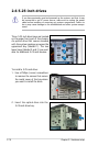
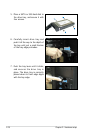
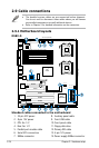
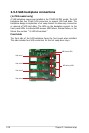
2.9 Cable connections
• The bundled system cables are pre-connected before shipment.
You do not need to disconnect these cables unless you will remove
pre-installed components to install additional devices.
• Refer to Chapter 4 for detailed information on the connectors.
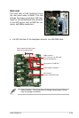
Standard cables connected to the motherboard
1. 24-pin ATX power
2. 8-pin 12V power
3. CPU fan 1/2
4. Rear fan 1/2
5. Parellel port module cable
6. Serial ATA connectors
7. SMBus connector
11
6
8
7
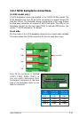
2.9.1 Motherboard layouts
DSBV-D
8Mb
FWH
KBPWR1
ATXPWR1
FLOPPY1
ATI
ES1000
BUZZER1
COM2
Super
I/O
CR2032 3V
Lithium Cell
CMOS Power
PANEL1
PS/2
T: Mouse
B: Keyboard
USB1
USB2
RJ-45
(LAN1)
ATX12V1
CPU_FAN1
Intel
®
6321ESB
PSUSMB1
BPSMB1
AUX_PANEL1
HDLED1
USB34
USBPW34
LAN_BW1
LPT1
USBPW12
DSBV-D
ASMB3
Intel
®
5000V
PCIE1
FB-DIMM_00 (64/72 bit, 240-pin module)
26.7cm (10.5in)
30.5cm (12in)
COM1
VGA1
PCIE2
PCIX5
PCIX4
PCI3
PCIX6
REAR_FAN2
ATX12V2
PRI_IDE1
FRNT_FAN2
SATA2
SATA1
SGIOP1
RECOVERY1
VGA_EN1
LAN_EN1
DIP_SW1
RJ-45
(LAN2)
FB-DIMM_01 (64/72 bit, 240-pin module)
FB-DIMM_02 (64/72 bit, 240-pin module)
FB-DIMM_10 (64/72 bit, 240-pin module)
FB-DIMM_11 (64/72 bit, 240-pin module)
FB-DIMM_12 (64/72 bit, 240-pin module)
CPU1
CPU2
FRNT_FAN1
FRNT_FAN4
FRNT_FAN3
CPU_FAN2
REAR_FAN1
CLRTC1
FBD_FAN1
RAID_SEL1
SATA4
SATA3
SATA6
SATA5
Intel
®
82563EB
+12V4LED1
SB_PWR1
1
2
3
3
4
9
12
10
5
13
14
8. Auxiliary panel cable
9. Front USB cable
10. Front panel cable
11. Floppy disk drive
12. Primary IDE cable
13. 4-pin 12V power
14. Power supply SMBus connector