


2-27ASUS TS500-E4
SATA backplane jumper settings and HDD ID assignments
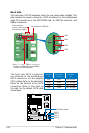
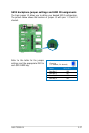
The 6-pin jumper J3 allows you to dene your desired SATA conguration.
The picture below shows the location of jumper J3 with pins 1-3 and 2-4
shorted.
Refer to the table for the jumper
settings and the appropriate ID# for
each SATA HDD bay.
J3 setting
(1-3 shorted, 2-4 shorted)
Device SATA ID #
Drive Bay 1 ID0
Drive Bay 2 ID1
Drive Bay 3 ID2
Drive Bay 4 ID3