


Chapter 2: Hardware setup2-26
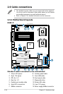
8Mb
FWH
KBPWR1
ATXPWR1
FLOPPY1
ATI
ES1000
BUZZER1
COM2
Super
I/O
CR2032 3V
Lithium Cell
CMOS Power
PANEL1
PS/2
T: Mouse
B: Keyboard
USB1
USB2
RJ-45
(LAN1)
ATX12V1
CPU_FAN1
Intel
®
6321ESB
PSUSMB1
BPSMB1
AUX_PANEL1
HDLED1
USB34
USBPW34
LAN_BW1
LPT1
USBPW12
DSBV-D
ASMB3
Intel
®
5000V
PCIE1
FB-DIMM_00 (64/72 bit, 240-pin module)
26.7cm (10.5in)
30.5cm (12in)
COM1
VGA1
PCIE2
PCIX5
PCIX4
PCI3
PCIX6
REAR_FAN2
ATX12V2
PRI_IDE1
FRNT_FAN2
SATA2
SATA1
SGIOP1
RECOVERY1
VGA_EN1
LAN_EN1
DIP_SW1
RJ-45
(LAN2)
FB-DIMM_01 (64/72 bit, 240-pin module)
FB-DIMM_02 (64/72 bit, 240-pin module)
FB-DIMM_10 (64/72 bit, 240-pin module)
FB-DIMM_11 (64/72 bit, 240-pin module)
FB-DIMM_12 (64/72 bit, 240-pin module)
CPU1
CPU2
FRNT_FAN1
FRNT_FAN4
FRNT_FAN3
CPU_FAN2
REAR_FAN1
CLRTC1
FBD_FAN1
RAID_SEL1
SATA4
SATA3
SATA6
SATA5
Intel
®
82563EB
+12V4LED1
SB_PWR1
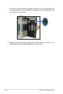
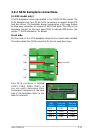
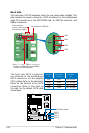
Back side
The back side of SATA backplane faces the rear panel when installed. This
side includes the power connectors, SATA interfaces for the motherboard
Serial ATA connectors or the SATA/RAID card, an HDD fan connector, and
SMBus connectors.
Fan connector (for HDD fan)
Power connectors
(connect power plugs
from the power supply)
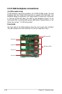
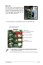
The back side SATA connectors
are attached to the motherboard
SATA connectors via the supplied
SATA cables. Refer to the illustration
below for the location of the SATA
connectors. Refer to the table on
the right for the default SATA cable
connections.
Backplane Connected to Controlled
ID
(on motherboard)
by
CON2 SATA1 Intel
®
6321ESB
CON4 SATA2 Intel
®
6321ESB
CON6 SATA3 Intel
®
6321ESB
CON8 SATA4 Intel
®
6321ESB
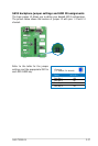
Upper 6-1 pins: SMBus connector
(connects the SMB cable from the BPSMB1
connector on the motherboard)
SATA RAID controller
SATA 2
SATA 1
SATA 4
SATA 3
CON2
CON4
CON6
CON8