


2-47ASUS TS500-E4
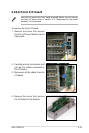
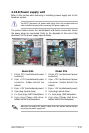
2.10.8 Power supply unit
Refer to this section when removing or installing a power supply unit to the
barebone system.
You MUST disconnect all power cable plugs from the motherboard and
other installed devices before removing the power supply unit.
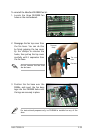
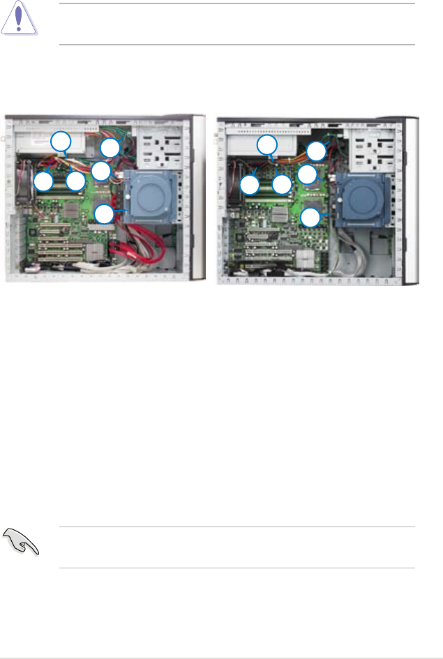
The picture below shows the motherboard and device connectors where
the power plugs are connected. Refer to the Appendix at the end of this
document for the power supply specications.
2
1
3
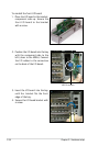
Model PA4
1. 24-pin ATX (motherboard power
connector)
2. 4-pin +12V (motherboard power
connector, hidden behind the
cables)
3. 8-pin +12V (motherboard power)
4. 4-pin plug (optical drive)
5. 2 x 4-pin plugs (SATA backplane)
6. 4-pin plug (floppy disk drive,
hidden behind the backplane)
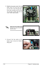
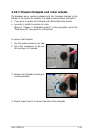
Model PX4
1. 24-pin ATX (motherboard power
connector)
2. 4-pin +12V (motherboard power
connector, hidden behind the
cables)
3. 8-pin +12V (motherboard power)
4. 4-pin plug (optical drive)
5. 2 x 4-pin plugs (SAS backplane)
6. 4-pin plug (floppy disk drive,
hidden behind the backplane)
5
6
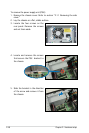
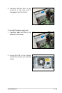
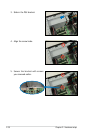
Make sure to unplug ALL power cables from the system devices before
removing the power supply unit.
4
2
1
3
5
6
4