


DISTRIBUTED COMMUNICATIONS SYSTEM (DCS) 6-3
_ ______________________________________________________________________________________
_ ______________________________________________________________________________________
_ ______________________________________________________________________________________
Tie Trunks
In ETNs, the tie trunks connecting DCS nodes are intermachine tie trunks. On the System 75 and Generic 1
communications system, they are administered as tandem trunks; while on the DIMENSION, System 85, and
Generic 2 communications system, they are type 41 trunks. In MS/T networks, on the System 75 and
Generic 1 communications system, the tie trunks are administered as tie; while on the DIMENSION, System
85, and Generic 2 communications system, they are designated with a trunk type of 78. See the Trunking
section of chapter 1 for more details on how these links should be administered.
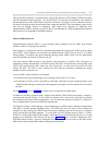
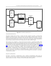
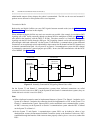
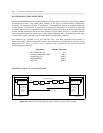
Signaling Links
The signaling links physically connecting DCS nodes are processor interface (PI) links on the System 75
and Generic 1 communications system; on the DIMENSION, System 85, and Generic 2 communications
system, they are data communications interface unit (DCIU) links.
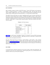
Each physical PI/DCIU link contains a set number of logical channels. For features to work transparently,
the switches involved in a connection must be provided with a dedicated logical channel over which the
DCS signals are transmitted. The number of physical links available on each switch, with the
corresponding number of channels per link are given below:
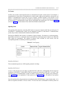
Table 6-2. Link Capacity
_ __________________________________________________________
Switch Physical Links Logical Channels/Link
_ __________________________________________________________
_ __________________________________________________________
DIMENSION 4 20
System 75, R1V2 and V3 4 64
Generic 1 2 sets of 4 64
System 85 8 64
Generic 2 8 64
_ __________________________________________________________
Signaling Link Speed
The recommended speed over a DCS signaling channel is 9.6 kbps.
Signaling Link Protocol
At layer 1 (the physical layer), the links are either RS-232C or RS-449. (Although RS-449 is the physical
connection on the DCIU, a cable [PEC 65259] can convert the connection to RS-232C.) At layer 2 (the
data-link layer), all communications systems use BX.25 protocol over their signaling link connections.
(See appendix D for an explanation of these protocols, and appendix E for a the physical layer pinout
explanations.)
Over the signaling link, all transmissions are numbered and the DCIU/PI keeps a copy of each packet. As it
sends out a packet, the DCIU or PI sets a timer. If it does not receive confirmation of delivery before an